UA Apollo X8: ASIO Resync Request Calibration Error [Windows 11]

Lumberjack88

Registered
Thread Starter
Joined
Jul 11, 2024
Messages
4
I'm new to REW and I tried to follow a youtube tutorial to set up my Apollo X8 for future measurements.

However, just before the calibration really starts, I constantly get this error:

ASIO device has been reset due to resync request from drive

I tried different sample rates (44.1, 48 and 96kHz) along with different sample buffer sizes (from 64 to 2048), I payed attention that the sample rate of the interface matches the chosen sample rate inside REW and I still get the same error message.

Maybe the level difference between the output versus the input is too big. It's currently 8 dB, as I've set my Apollo X8 line out level to -10dBv and left my Hi-Z input level at 0. With a -20 dBFS REW test signal, I get a level of -12.8 dBFS back that way. If I'd use the normal line level of +4 dBu, then the input is almost redlining. I could use the line input on the back for closer level matching, however, for the tests I'm doing, I have to use the Hi-Z input, because I want to test reamp boxes that basically turn low impedance line level signals into high impedance instrument level signals.

I'm using the Apollo X8 (latest FW) on my Windows 11 (lateset version) PC with an AMD 5950x CPU and it's connected via an active Thunderbolt 3 cable directly to a Thunderbolt 3 port on my mainboard, without adapters etc.

How can I fix this problem?
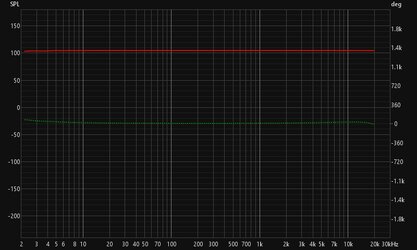
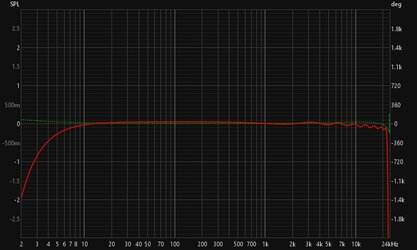
 

Lumberjack88

Registered
Thread Starter
Joined
Jul 11, 2024
Messages
4
It might be difficult, see this thread:

Try the WASAPI Exclusive drivers: select Java instead of ASIO as the driver and choose device names that start EXCL.
When I choose Java and the EXCL entry labeled as "Speakers (Universal Audio Thunderbolt WDM)" I get this error message:

Unable to access the selected device due to

EXCL: Speakers (Universal Audio Thunderbolt WDM) does not have any lines supporting PCM_SIGNED 48000.0 Hz, 32 bit, stereo, 8 bytes/frame, little-endian

Try a different sample rate

Check that the sample rate of the default format in the Windows audio properties for the device matches the REW sample rate.


I've checked the sample rates and the ones in the windows audio settings match the ones that I'm using in my UA preferences as well as those that I chose in REW.

To get back to the ASIO mode: Even though I kept getting the resync request error, I still proceeded with the test process and the graph that I got is included as an attachement. Is it normal to get a 105 SPL signal when the level calibration has shown a 7ish dB difference between the -20dBFS test signal and the Hi-Z input signal? Is this kind of calibration file useful or simply wrong? It does look very linear, which is to be expected, but maybe it's still wrong...
 

Attachments

  • calibration.jpg
    calibration.jpg
    50.2 KB · Views: 6

John Mulcahy

REW Author
Joined
Apr 3, 2017
Messages
7,866
Looks good, though the SPL span is very, very large - most things would look flat on that scale :). No obvious issues though. The SPL figures themselves don't mean much until the SPL reading has been calibrated, but the cal file generates values relative to the level at 1 kHz so the absolute SPL makes no difference to that.
 

Lumberjack88

Registered
Thread Starter
Joined
Jul 11, 2024
Messages
4
So there's no problem with using this as my calibration file?

Also, from a physics perspective, do you think it makes sense to test a reamp box linearity, i.e. transformer linearity since it's not much more than that inside those boxes, by using this signal chain:

Balanced Line Out Audio Interface -> TRS/TRS cable -> Reamp Box Balanced Input-> Unbalanced High Impedance Reamp Box Output - > TS/TS cable -> Hi-Z input Audio Interface

The calibration that I did just now is based on this:

Balanced Line Out Audio Interface -> TS/TS cable -> Unbalanced Hi-Z Input Audio Interface

Would this lead to a meaningful linearity comparison when I calibrate REW the way I did just now?

EDIT: I redid the calibration and this is the new measurement that I'm getting.

Is this closer to what it's supposed to look like rather than that 105 SPL flat line that I got from my first calibration attempt?
 

Attachments

  • calibration_new_main.jpg
    calibration_new_main.jpg
    53.5 KB · Views: 8
Last edited:

John Mulcahy

REW Author
Joined
Apr 3, 2017
Messages
7,866
Yes, looks good. There are two aims for the loopback cal, making sure monitoring is off and accounting for response roll-offs. For acoustic measurements it is rare to find an interface whose roll-offs are significant. For maximum accuracy (e.g. when measuring component electrical responses) the loopback cal should cover the whole measurement chain apart from the system being measured, which is replaced by a cable connection.
 

Lumberjack88

Registered
Thread Starter
Joined
Jul 11, 2024
Messages
4
Yes, looks good. There are two aims for the loopback cal, making sure monitoring is off and accounting for response roll-offs. For acoustic measurements it is rare to find an interface whose roll-offs are significant. For maximum accuracy (e.g. when measuring component electrical responses) the loopback cal should cover the whole measurement chain apart from the system being measured, which is replaced by a cable connection.
I'm really liking the application so far! Thanks for creating it!

I just have one little question: Is it possible to move, i.e. offset, graphs other than the SPL (like dBFS), so that we can align multiple graphs down to 0.01dB precision on the y-axis, which isn't quite possible with outboard gear?

I know that offest can already do this for SPL, I just hope there's a similar alternative for the other type of graphs! That way, little differences can be much easier to spot between different measured hardware units!
 

John Mulcahy

REW Author
Joined
Apr 3, 2017
Messages
7,866
Sorry, there isn't. The SPL values are an offset from the underlying dBFS data, so the shift is just changing that offset - the underlying data isn't changed. However, you can calibrate the SPL reading to read the same as dBFS by just entering the appropriate figure when calibrating.
 
Top Bottom