To delay or not

linuxonly

Member
Thread Starter
Joined
Jul 27, 2024
Posts
112
More  
Preamp, Processor or Receiver
Logitech Z906
DAC
AMD FCH Azalia
Computer Audio
SPDIF output with alsa, pipewire, wireplumber on Fedora 40
Streaming Equipment
Kodi
Front Height Speakers
33 in
Middle Height Speakers
30 in
Rear Height Speakers
57 in
Video Display Device
X11/VGA + X11/DVI
Hi.

Following @moedra tutorial https://www.avnirvana.com/threads/convolution-room-correction-and-room-curve.14005/ using one set of measurements and IR filters for the listening room where the front speakers are equidistant from the MLP, I'm getting used to it after repeating the process again and again for refinement.

In the same listening room however, I have a 2nd listening position facing a 2nd screen (computer screen at 90 degrees left from the main). I took another set of measurements with the mic positioned where the seat is and generated new IR filters. One speaker is 3 ft away from the seat whereas the other (the reference) is at 9 ft. I wonder whether or not I shall apply a 6 ms delay to the closest speaker to get them in phase again? Maybe it's already part of the correction, I'm not sure about that. The speakers are screwed on the walls so moving them is not an option. On top of that their position is already optimized for the first case. In case one wonders how it's possible to turn left 90 degrees and still have FL and FR speakers, I remapped the FL channel to the RL speaker and the FR channel to the FL speaker. In other words, I'm facing the left wall. I have a different CamillaDSP for each case and I switch depending if I watch a movie, listen to music (main, facing front) or play a game (at the keyboard, facing left).
 

linuxonly

Member
Thread Starter
Joined
Jul 27, 2024
Posts
112
More  
Preamp, Processor or Receiver
Logitech Z906
DAC
AMD FCH Azalia
Computer Audio
SPDIF output with alsa, pipewire, wireplumber on Fedora 40
Streaming Equipment
Kodi
Front Height Speakers
33 in
Middle Height Speakers
30 in
Rear Height Speakers
57 in
Video Display Device
X11/VGA + X11/DVI
Another question.

I took measurements for 6 speakers on a 5.1 system and for each speaker I got something like
Code:
Delay 3.9500 ms (1.355 m, 4 ft 5.3 in)
using IR start time relative to Acoustic reference played from LINE_OUT L with no timing offset
Clock adjustment: -232.0 ppm

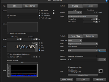
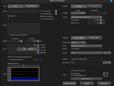
1 - For given speaker, the delay is not constant. It changes constantly from -2 ms to 6 ms. Why is that?

2 - Let's suppose I have the following results on measurements at the MLP

FL: -0.025 ms
FR: 0.34
FC: -1.96
FLE: 1.99
BL: -0.26
BR: 0.03

How would you apply those delays to CamillaDSP? I tried entering them as they are and got a ' Invalid filter 'delay_l'. Reason: Delay cannot be negative' error, e.g.

Code:
  delay_fr:
    type: Delay
    parameters:
      delay: 0.0352
      unit: ms
      subsample: false

I mean what values would you enter to time align? This isn't clear to me.
 

JStewart

Senior AV Addict
Supporter
Joined
Dec 5, 2017
Posts
2,371
Location
Central FL
1 - For given speaker, the delay is not constant. It changes constantly from -2 ms to 6 ms. Why is that?
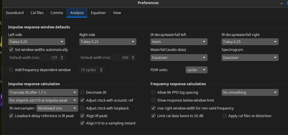
Not sure.. are you using a usb mic? on the analysis preferences tab is the box checked for:

The Adjust clock with acoustic ref selection controls whether REW compensates for clock rate differences between input and output when using the acoustic timing reference. If this option is selected an additional timing reference signal is played at at the end of the sweep and the time between the timing reference signals is used to calculate any clock adjustment required to match the input and output device clock rates.

2 - Let's suppose I have the following results on measurements at the MLP

FL: -0.025 ms
FR: 0.34
FC: -1.96
FLE: 1.99
BL: -0.26
BR: 0.03

How would you apply those delays to CamillaDSP? I tried entering them as they are and got a ' Invalid filter 'delay_l'. Reason: Delay cannot be negative' error, e.g.

I haven’t used Camilla, but to get rid of the negatives make FC 0 and add 1.96 to every other speaker’s delay.
 

linuxonly

Member
Thread Starter
Joined
Jul 27, 2024
Posts
112
More  
Preamp, Processor or Receiver
Logitech Z906
DAC
AMD FCH Azalia
Computer Audio
SPDIF output with alsa, pipewire, wireplumber on Fedora 40
Streaming Equipment
Kodi
Front Height Speakers
33 in
Middle Height Speakers
30 in
Rear Height Speakers
57 in
Video Display Device
X11/VGA + X11/DVI
Not sure.. are you using a usb mic? on the analysis preferences tab is the box checked for:

The Adjust clock with acoustic ref selection controls whether REW compensates for clock rate differences between input and output when using the acoustic timing reference. If this option is selected an additional timing reference signal is played at at the end of the sweep and the time between the timing reference signals is used to calculate any clock adjustment required to match the input and output device clock rates.

Yes, UMIK-1.

Capture d’écran du 2024-09-27 22-11-58.png Capture d’écran du 2024-09-27 22-12-25.png
I haven’t used Camilla, but to get rid of the negatives make FC 0 and add 1.96 to every other speaker’s delay.

Oh thanks, will try that and let you know.
 

Attachments

  • Capture d’écran du 2024-09-27 22-12-25.png
    Capture d’écran du 2024-09-27 22-12-25.png
    91 KB · Views: 9

linuxonly

Member
Thread Starter
Joined
Jul 27, 2024
Posts
112
More  
Preamp, Processor or Receiver
Logitech Z906
DAC
AMD FCH Azalia
Computer Audio
SPDIF output with alsa, pipewire, wireplumber on Fedora 40
Streaming Equipment
Kodi
Front Height Speakers
33 in
Middle Height Speakers
30 in
Rear Height Speakers
57 in
Video Display Device
X11/VGA + X11/DVI
Here's the result. The LFE is probably not meaningful but the other delays make some sense. The FC is the closest to the MLP. Is that all there is to do? First generate the convolution filters, then apply the delays given by the measurements to the DSP. Simple as that?

Code:
  delay_l:
    type: Delay
    parameters:
      delay: 1.9322
      unit: ms
      subsample: false
  delay_r:
    type: Delay
    parameters:
      delay: 2.2986
      unit: ms
      subsample: false
  delay_c:
    type: Delay
    parameters:
      delay: 0
      unit: ms
      subsample: false
  delay_lfe:
    type: Delay
    parameters:
      delay: 3.9483
      unit: ms
      subsample: false
  delay_rl:
    type: Delay
    parameters:
      delay: 1.6916
      unit: ms
      subsample: false
  delay_rr:
    type: Delay
    parameters:
      delay: 1.9919
      unit: ms
      subsample: false

Clipboard01b.jpg

On second thought isn't it counter intuitive? Adding delays to the farthest speakers seems the inverse of the proper thing to do...

So I negated all measurement delays, got rid of the negatives with an offset. Makes sense?

Code:
 delay_l:
    type: Delay
    parameters:
      delay: 0.3664
      unit: ms
      subsample: false
  delay_r:
    type: Delay
    parameters:
      delay: 0
      unit: ms
      subsample: false
  delay_c:
    type: Delay
    parameters:
      delay: 2.2986
      unit: ms
      subsample: false
  delay_lfe:
    type: Delay
    parameters:
      delay: 0
      unit: ms
      subsample: false
  delay_rl:
    type: Delay
    parameters:
      delay: 0.607
      unit: ms
      subsample: false
  delay_rr:
    type: Delay
    parameters:
      delay: 0.3067
      unit: ms
      subsample: false
 
Last edited:

JStewart

Senior AV Addict
Supporter
Joined
Dec 5, 2017
Posts
2,371
Location
Central FL
My bad. The numbers in post 1 are time of flight differences relative to your left speaker, correct?
Delays are calculated relative to farthest speaker as you said. It is 0 delay. All other speakers delayed to match.

See if this makes sense:

Relative to FLRelative to Each OtherRelative to Farthest Speaker
FL
-0.0250​
1.9350​
2.0150​
FR
0.3400​
2.3000​
1.6500​
FC
-1.9600​
0.0000​
3.9500​
FLE
1.9900​
3.9500​
0.0000​
BL
-0.2600​
1.7000​
2.2500​
BR
0.0300​
1.9900​
1.9600​

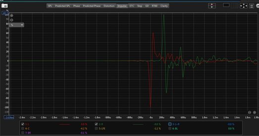
Hard for me to see in post 5, but it looks like maybe front right is reversed in polarity on impulse chart?

Is FLE a subwoofer? If so it may be best aligned at the timing that provides the best phase matching at the crossover between it and the fronts phase or center phase. A subject for another day perhaps.

1 - For given speaker, the delay is not constant. It changes constantly from -2 ms to 6 ms. Why is that?
Is this still the case? The time of flight relative to the same timing reference speaker shouldn't change. The difference you mention is approx 8 feet.
 

linuxonly

Member
Thread Starter
Joined
Jul 27, 2024
Posts
112
More  
Preamp, Processor or Receiver
Logitech Z906
DAC
AMD FCH Azalia
Computer Audio
SPDIF output with alsa, pipewire, wireplumber on Fedora 40
Streaming Equipment
Kodi
Front Height Speakers
33 in
Middle Height Speakers
30 in
Rear Height Speakers
57 in
Video Display Device
X11/VGA + X11/DVI
My bad. The numbers in post 1 are time of flight differences relative to your left speaker, correct?
Hi, thanks for your interest!
Yes that is correct, FL is the reference.
Delays are calculated relative to farthest speaker as you said. It is 0 delay. All other speakers delayed to match.

See if this makes sense:

Relative to FLRelative to Each OtherRelative to Farthest Speaker
FL
-0.0250​
1.9350​
2.0150​
FR
0.3400​
2.3000​
1.6500​
FC
-1.9600​
0.0000​
3.9500​
FLE
1.9900​
3.9500​
0.0000​
BL
-0.2600​
1.7000​
2.2500​
BR
0.0300​
1.9900​
1.9600​

Oh I understand the point.

You presumed the farthest speaker would be FC, it's not the case. In fact the main and surround speakers are 2 meters to MLP plus or minus 30cm whereas the FC and LFE are at 1m50 and 1m60 respectively. Therefore the farthest speaker whould be FR, by 5 cms and my numbers are probably closer to reality by a hair. Thanks a lot for the clarification. Mucho apprecietado.

I didn't take LFE into account because its reported delay (1.9916) doesn't make any sense. I mean 2 ft is correct, but in the wrong direction. That's why I didn't add any delay (yet) to the LFE, not knowing how to deal with it, I ignored it for the time being.

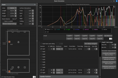
Here's the room simulation with the proper distances.

Capture d’écran du 2024-09-28 12-59-40.png

Here are my calculations assuming the farthest speaker is FR. Method 1 is yours; medhod 2 is the one I used yesterday. For the moment i negated LFE to reflect reality. It's experimental and doesn't change an iota to other delays.

Capture d’écran du 2024-09-28 14-13-17.png


I'm including the mdat. I'm interested to see what would you suggest.

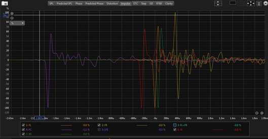
Hard for me to see in post 5, but it looks like maybe front right is reversed in polarity on impulse chart?
It looks like so, however the polarity is correct. Checked and double checked.
Is FLE a subwoofer? If so it may be best aligned at the timing that provides the best phase matching at the crossover between it and the fronts phase or center phase. A subject for another day perhaps.
Noted. Will research the subject. It is indeed a subwoofer.

Is this still the case? The time of flight relative to the same timing reference speaker shouldn't change. The difference you mention is approx 8 feet.
It happens from time to time, with a warning from REW. So I took the habit to take 2 measurements and if the timings differ, I take a 3rd one and so on until I have found the proper one.
 

Attachments

  • CMI8738-6ch-analog.mdat
    9.5 MB · Views: 3,686
Last edited:

JStewart

Senior AV Addict
Supporter
Joined
Dec 5, 2017
Posts
2,371
Location
Central FL
Here are my calculations assuming the farthest speaker is FR. Method 1 is yours; medhod 2 is the one I used yesterday. For the moment i negated LFE to reflect reality. It's experimental and doesn't change an iota to other delays.
Same exact relative delays with the numbers in the table with the LFE.

Thanks for posting the .mdat.
I took a look at the front left/right. Something is clearly going on.
This screenshot is using the alignment tool.
1/6 smoothing has been applied to improve visibility.
Red/Green are front left and right. In a perfect world when summed, the sum will be 6dB higher than the individuals (assuming they were 100% identical to begin with, but you get the idea) This Sum is represented by the top dotted black line.
The Blue line is what was obtained when the speakers were measured together. Its below the separate measurements from 100Hz to 270 Hz and well below the perfect world possible summation (dotted black line). The phase traces on the lower trace show the reason.
The solid black line the mirrors your R/L (Blue) measurement is REW's calculation of the sum of the two taking phase into consideration.

2024-09-28.png


The below chart shows:
Purple - A+B (best possible)
Black - Right + Left measurement
Green - Right + Left measurement with Right inverted polarity.

2024-09-28 (4).png


There's definitely some kind of phase issue going on and it doesn't look like reversing the speaker wires will resolve it.
Best guess is the sub interacting differently with the right vs the left. Swapping the left and right speakers and re-measuring would prove or dis-prove.
 

linuxonly

Member
Thread Starter
Joined
Jul 27, 2024
Posts
112
More  
Preamp, Processor or Receiver
Logitech Z906
DAC
AMD FCH Azalia
Computer Audio
SPDIF output with alsa, pipewire, wireplumber on Fedora 40
Streaming Equipment
Kodi
Front Height Speakers
33 in
Middle Height Speakers
30 in
Rear Height Speakers
57 in
Video Display Device
X11/VGA + X11/DVI
Same exact relative delays with the numbers in the table with the LFE.

Thanks for posting the .mdat.
I took a look at the front left/right. Something is clearly going on.
This screenshot is using the alignment tool.
1/6 smoothing has been applied to improve visibility.
Red/Green are front left and right. In a perfect world when summed, the sum will be 6dB higher than the individuals (assuming they were 100% identical to begin with, but you get the idea) This Sum is represented by the top dotted black line.
The Blue line is what was obtained when the speakers were measured together. Its below the separate measurements from 100Hz to 270 Hz and well below the perfect world possible summation (dotted black line). The phase traces on the lower trace show the reason.
The solid black line the mirrors your R/L (Blue) measurement is REW's calculation of the sum of the two taking phase into consideration.

View attachment 74047

The below chart shows:
Purple - A+B (best possible)
Black - Right + Left measurement
Green - Right + Left measurement with Right inverted polarity.

View attachment 74048

There's definitely some kind of phase issue going on and it doesn't look like reversing the speaker wires will resolve it.
Best guess is the sub interacting differently with the right vs the left. Swapping the left and right speakers and re-measuring would prove or dis-prove.
Very interesting, thanks for your enlightening analysis. I'm however not familiar with the alignment tool. In fact I discovered it yesterday.

For the record, the first set of IR filters I made was made, 6 weeks ago or so, with L and R time aligned at 0. Because the author created an AVG(L.R) that was used to create an unique IR filter to be applied to both channels.

With @moedra method, there is no such thing as time alignment and I presumed, correct me if I'm wrong that since there were timing references resent, REW would handle that magically in creating the IR filters.

My first reaction to your analysis is that the room is imperfect. OK it's rectangular but there are 2 windows, 3 opened doors, 1 closed steel door, a corridor leading to a large room, a computer table, seats and a sofa. Room has nodes. Its's expected the curves will be far from perfect. Hence all the work we do here to correct them.

I understand your point regarding the addition of L+R and the expected results. However like I said I'm not familiar with the alignment tool and am not able to interpret the graphs.

I looked another set of measurements I made a few weeks ago, with another sound card on the same computer and they present the same characteristics you saw on the impulse graph posted earlier. Sound card now out of the equation.

With the measurements included in the mdat I posted earlier, I generated IR filters, put them in CDSP (no delays added yet) and measured again to see the results of the correction. Here we go.

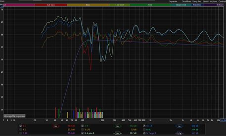
On the following graph, the whitish line is the vectorial sum of L+R, the blue line is the measured L+R, and the target is in purple. If you see traces below 95 Hz, the Z906 generates them internally from the LFE.
I still see problems between 175-300Hz where the sum is below L and R. Nodes maybe, electronics issues with the Z906, I don't know. The traditional method to test electronics would be to fed a square wave to the channel to test and look at the results on the scope, a dummy load in place of the speaker.

after-correction2.jpg

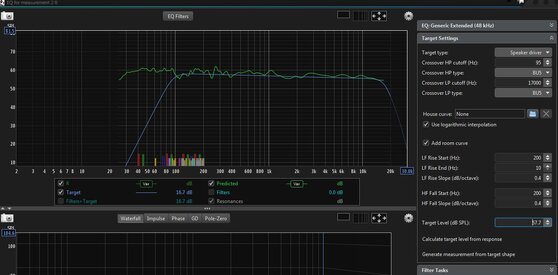
Correction for the left channel:
after-correction3.jpg

Impulse response, R is in green.
after-correction1.jpg


It's recommended to optimize speaker placement and apply rom treatment before generating filters. I placed the speaker in the best place I could (one is even screwed on a steel door). No form of room treatment yet. It's expensive and the results are uncertain because of my lack of knowledge on that matter. So I proceeded the other way around, by generating filters on an unoptimized/untreated room. Due to the amount of electronic equipment and wires going below the floor between them, furnitures are at their definitive placement. Speakers are screwed on the walls. And the subwoofer contains all the electronics and therefore all input/output/power wires are connecting there. It's immuable. As I said, speakers wires are run below the floor to the speakers.

Do you see improvements after correction with the curves above in mind? Flaws? Problems ignored by the correction? Place for more improvement?

Last question. How to fix then?

Best regards!
 

JStewart

Senior AV Addict
Supporter
Joined
Dec 5, 2017
Posts
2,371
Location
Central FL
I'm however not familiar with the alignment tool.
In this case I used it because it showed all the relevant traces. It’s typically used to align subwoofers to mains to find optimal phase alignment which provides best SPL through the XO

With @moedra method, there is no such thing as time alignment and I presumed, correct me if I'm wrong that since there were timing references resent, REW would handle that magically in creating the IR filters.
No magic applied. Speakers need to be aligned separately with the method.

My first reaction to your analysis is that the room is imperfect.
I don’t think that’s the cause here, but I’m not knowledgeable enough to say for sure. I do think it’s related to the FR position and not a defect or wiring problem. My guess is subwoofer interaction with the right is different than the left. I suppose the end result is kinda the same though. If FL and FR could be measured without the sub that would be ideal. Absent that you could exchange the FL and FR connections to the sub and re-measure to confirm.

Do you see improvements after correction with the curves above in mind? Flaws? Problems ignored by the correction? Place for more improvement?

Assuming a root cause for the FR phase shift can’t be corrected by other means, you could perhaps use an AllPass filter in Camilla DSP to correct the FR phase in the problem region, to some extent. I’m not familiar with Camilla, so I can’t help with how it's input, or if one can do it with the current filters also engaged.
There’s also a free tool called RePhase that I’m pretty sure would do it. It's should do a more exacting job than all pass filters. I wouldn’t be able to help here either, unfortunately.

An 2nd order all pass filter applies a 180deg phase shift (therefore inversion) at its center frequency and slopes to 0deg phase shift at either end. It does this without changing the frequency response.

Here is the effect of an all pass filter applied to the FR measurement from the .mdat supplied earlier.
Specifically 2nd order (which I'm guessing is camilla default) centered at 400Hz with a Q of 1.41 which equals a bandwidth of 1 octave, so in this case 200Hz to 800Hz.

Purple Line is FR + FL without regard to phase.
Green is the FR/FL together measurement
Blue has the AllPass filter applied to the FR speaker and then the FL and FR are calculated with phase taken into account.

Comparison w-AllPass.png


With the measurements included in the mdat I posted earlier, I generated IR filters, put them in CDSP (no delays added yet) and measured again to see the results of the correction. Here we go.
Eyeballing the resulting response you could try an AllPass centered at 240Hz and a Q of 4.5. It's not going to be optimized because of eyeballing from the chart, but you'll be able to listen to and measure the results. Be curious if the FR impulse response is corrected with the allpass applied, too.

So my recommendation from here would be to finalize the delays you want to use by re-measuring with a timing reference. When remeasuring for a timing reference I would use a bandwidth of 500Hz to 2500Hz (which is think is the bandwidth of the acoustic timing chirp in REW). This will leave out the subwoofer, just in case it's interfering with the impulse peak timing of the satellites.

Setting the sub delay, I don't know. It seems like it will be an iterative process with your setup because any change to it's timing is likely to affect all the other speakers response.

Once delays are set, finalize the filters you want to use. Normally the process is filters first then delays, but in this case I'm assuming the any change to the sub delay is likely to have a larger impact on phase than filter changes will.

After applying final filters and delays take another set of full range measurements for FL and FR and calculate an allpass filter or use rephase for final correction if desired.

I would appreciate any input from other forum members on any aspect of this. I feel reasonably confident, but I''m by no means an expert. A key point is the OP can't measure the sub and sats separately as the sub feeds the signal to the sats.
 

linuxonly

Member
Thread Starter
Joined
Jul 27, 2024
Posts
112
More  
Preamp, Processor or Receiver
Logitech Z906
DAC
AMD FCH Azalia
Computer Audio
SPDIF output with alsa, pipewire, wireplumber on Fedora 40
Streaming Equipment
Kodi
Front Height Speakers
33 in
Middle Height Speakers
30 in
Rear Height Speakers
57 in
Video Display Device
X11/VGA + X11/DVI
A key point is the OP can't measure the sub and sats separately as the sub feeds the signal to the sats.

Well technically I could turn it off if I get the signal through the alsa looback by not feeding anything to the LFE channel as I added 30 db/oct 95Hz HPF to all satellites to minimise crosstalk. It's the low Fc of my target curve. On the sub, I have a 30 db/oct LPF at 80 Hz.

Amazing. Thanks so much. Food for thought. In the meantime, I'm attaching measurements with the L and R speakers swapped. In other words, the L curve is generated by the R speaker and vice-versa.
 

Attachments

  • CMI8738-L-R-swapped.mdat
    2.5 MB · Views: 3,997
Last edited:
Top Bottom