


-
AUDIO VIDEO PROCESSING, SETUP & ENVIRONMENTOfficial REW (Room EQ Wizard) Support Forum Audiolense User Forum Calibration Equipment Auto-EQ Platforms / Immersive Audio Codecs Video Display Technologies / Calibration AV System Setup and Support Listening Room / Home Theater Build Projects Room Acoustics and Treatments AV Showcase Movies / Music / TV / Streaming
-
AUDIO VIDEO DISCUSSION / EQUIPMENTHome Theater / Audio and Video - Misc Topics Essence For Hi Res Audio AV Equipment Advice and Pricing Awesome Deals and Budget AV Equipment AV Receivers / Processors / Amps UHD / Blu-ray / CD Players / Streaming Devices Two Channel Hi-Fi Equipment DIY Audio Projects Computer Systems - HTPC / Gaming HD and UHD Flat Screen Displays Projectors and Projection Screens AV Accessories Buy - Sell - Trade
Navigation
Install the app
How to install the app on iOS
Follow along with the video below to see how to install our site as a web app on your home screen.
Note: This feature may not be available in some browsers.
More options
You are using an out of date browser. It may not display this or other websites correctly.
You should upgrade or use an alternative browser.
You should upgrade or use an alternative browser.
Thiele-Small Parameters measurement using dual added mass method.
- Thread starter Bernard
- Start date

John Mulcahy
I measured a driver that has very low sensitivity. About 80 dB. During measurements, the sweep was very quiet. It's usually louder. Can the measurements be trusted in this case? Should there be a dependence of the level of the measuring signal on the sensitivity of the driver being measured?John Mulcahy
REW Author
- Joined
- Apr 3, 2017
- Posts
- 8,394
Dual added mass measurements include a Bℓ curve, it should be close to horizontal around the resonant frequency if the measurements are good.
John Mulcahy
REW Author
- Joined
- Apr 3, 2017
- Posts
- 8,394
It is the calculated power sensitivity, but it is generally better to use the manufacturer's figure.
Hello. Thanks for the invitation.if you have a Speakerbench-related question
To answer your question in post 77 about measurement level, the usual advice is to say that for good comparison with linear theory, the level needs to be high enough to have a good S/N ratio, but low enough to avoid nonlinearity. Practically this means something between 10mV and 500mV for 3in-8in drivers. For larger drivers and for modeling high-power applications, you will of course want higher voltages. Is there a specific question about Speakerbench?
Thanks for your clarification.To answer your question in post 77 about measurement level
John Mulcahy,
Does it matter at what signal level I calibrate the equipment before measuring the impedance? If I plan to measure impedance at levels of 100-700 mV, at what level should I calibrate? And if at the levels of 1.4-3 V, at what level should the calibration be done?John Mulcahy
REW Author
- Joined
- Apr 3, 2017
- Posts
- 8,394
No.Does it matter at what signal level I calibrate the equipment before measuring the impedance?
Thank you. The picture shows two tables of TS parameters created based on the same data. Left from REW, right from Speakerbench. I highlighted a small discrepancy in blue, and a large discrepancy in red. Is there anything that can be done to ensure that the parameters marked in red match closely?
Attachments
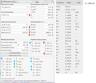
A lot of parameters have significantly more resolution than seems appropriate. Some measured parameters likely have a significant accuracy tolerance, depending on how the measurement was taken, and with what means, and whether the measurement was done at an appropriate location (eg. the voice coil resistance). It almost suggests the need to use a monte carlo simulation to appreciate what range a calculated parameter could end up with.


Popular tags
20th century fox
4k blu-ray
4k uhd
4k ultrahd
action
adventure
animated
animation
bass
blu-ray
calibration
comedy
comics
denon
dirac
dirac live
disney
dolby atmos
drama
fantasy
hdmi 2.1
home theater
horror
kaleidescape
klipsch
lionsgate
marantz
movies
onkyo
paramount
pioneer
rew
romance
sci-fi
scream factory
shout factory
sony
stormaudio
subwoofer
svs
terror
thriller
uhd
ultrahd
ultrahd 4k
universal
value electronics
warner
warner brothers
well go usa