Wrong thiele small parameters

brunohydra

Registered
Thread Starter
Joined
Oct 28, 2020
Posts
9
Hello.
A few weeks ago I had a problem with the impedance measure, I did a forum thread and the problem was solved.
Now, I did a measure of my speaker and I compared with the manufacture datasheet and the parameters are much different.
Manufacture parameters:
44922


Measured parameters:
TS Parameters file
Room EQ V5.20
Dated: 09/09/2021 02:07:32
From measurement Kaos BASS 1350 15"

Zmin 50.71 ohm
fmin 190 Hz
f3 11369 Hz
Le(f3) 0.375 mH
Motional impedance parameters
R0 299.12 ohm
CMES 1.189.1 uF
L0 5.702 mH
beta 0.0450
omega0 568.2
Blocked impedance parameters
RDC 2.80 ohm
dR 10.00 ohm
Re 50.64 ohm
Leb 80.6 uH
Le 1.811 mH
Rss 100000.0 ohm
Ke 0.1161 S-H
Thiele-Small parameters
fs 60.3 Hz
Qms 134.692
Qes 22.801
Qts 19.500
Fts 3.1
Mms 169.26 g
Cms 0.041 mm/N
Rms 0.476 kg/s
Vas 75.72 litres
Bl 11.931 Tm
Eta 0.07 %
Lp (1W/1m) 80.66 dB
Dd 38.10 cm
Sd 1140.1 cm^2
Added mass measurement: Kaos BASS 1350 15" 63
Added mass 63.000 g
Air temperature 20.0 C
Air pressure 1010.00 mB
Air density 1.2002 kg/m^3
Speed of sound 343.2 m/s

How my impedance measure is configured:
44923

44924

44925

44926


My question is:
Can I measure a 15" speaker with a soundcard?
If yes, what do I need to do to make this measure reliable?

Link of another post:
AVNIRVANA /threads/wrong-parameters-measured.9029/#post-70002
 

jschwender

Member
Joined
Mar 16, 2021
Posts
140
Location
GERMANY
More  
Front Speakers
Nubert digital pro
Other Speakers
Philips dss940
Generally yes, you can do that. The line output may not be the best choice, if your headphone output has a lower impedance it may work better. For better precision you utilize an additional power amplifier plugged to the line output. It does not need to be a 500 W monster, even if it is only a 5 W amplifier, that will have better results than without.
 

brunohydra

Registered
Thread Starter
Joined
Oct 28, 2020
Posts
9
Hello Jschwender.
Is this amplifier is good for this situation?

44933


I assume I will need to use a lower output volume, cause this 5W can destroy my line in.
Thinkin about the new circuit, it Is correct?

44934
 

trobbins

Member
VIP Supporter
Joined
Nov 26, 2017
Posts
128
Location
Australia
Does the amp module connect a speaker output internally to the 5V(neg)/audio in(neg) terminal?

The impedance measurement technique assumes the soundcard inputs and outputs all have a common gnd connection. The sense resistor must directly drive the device-under-test (your speaker) - like when measuring a test resistor - however your proposed scheme does not do that.
 

jschwender

Member
Joined
Mar 16, 2021
Posts
140
Location
GERMANY
More  
Front Speakers
Nubert digital pro
Other Speakers
Philips dss940
This amp is not usable for several reasons: 1. It has a bridge output: you must have non-bridge amp. 2. it is a class D amplifier: it has high distortion, high output noise. Analog amps are a better choice here. If your line in can handle the level depends on your specific sound card. Simple consumer soundcards have maximum input level of something like 1V, professional sound cards, (also called audio interfaces) can hande 10 V input and more without probems, you can easily connect them to a 20 W amplifier without problem. If you use a consumer grade sound card you should use a voltage divider, simply by two resistors.
 

brunohydra

Registered
Thread Starter
Joined
Oct 28, 2020
Posts
9
I have a TDA2003 amplifier it's a 10W analog amplifier. This problem is solved, now my question is:

How can I make the connection of the amplifier in the circuit?
 

trobbins

Member
VIP Supporter
Joined
Nov 26, 2017
Posts
128
Location
Australia
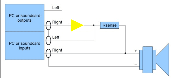
The soundcard output goes to the amp. The amp goes to the speaker. The sense resistor is between the amp and the speaker. The soundcard inputs go to either side of the sense resistor. Perhaps best if you modify your drawing and post it here, to confirm you appreciate what is being done.
 

jschwender

Member
Joined
Mar 16, 2021
Posts
140
Location
GERMANY
More  
Front Speakers
Nubert digital pro
Other Speakers
Philips dss940
This is how it looks like
 

Attachments

  • Impedance-setup.png
    Impedance-setup.png
    14.9 KB · Views: 34

trobbins

Member
VIP Supporter
Joined
Nov 26, 2017
Posts
128
Location
Australia
That's the correct arrangement of parts. The issue now is that your extra amplifier may generate too large a signal for your soundcard inputs. You could do the measurement with just enough soundcard output signal so as to just be under the soundcard input clip levels, or you could include resistor dividers to return an attenuated signal to each of the soundcard input. Using the resistor dividers may not introduce errors, as the calibration procedure could/should exclude them, but the divider resistors should be metal film and may need to be power rated so as not to introduce distortion depending on the resistance values used.
 

sm52

Member
Joined
Mar 14, 2019
Posts
1,008
but the divider resistors should be metal film and may need to be power rated so as not to introduce distortion depending on the resistance values used.
You are advising everything correctly. But I tried to calibrate with a divider across two resistors. Resistors are accurate, have a 1% nominal error. Everything worked out well in the entire frequency range. But when I looked at the GD plot, in the HF part, after 10 kHz there was a delay. And up to 20 kHz it increased exponentially. So I gave up the amplifier and divider. External sound card only. Then everything is fine.
 

brunohydra

Registered
Thread Starter
Joined
Oct 28, 2020
Posts
9
If I use a audio interface the signal is higher than a USB soundcard right?
I was looking for this audio Interface on Aliexpress.

45098


Will it solve my gain problem to measure the speaker?
It costs more than a amplifier, but I can use for measure another things too.
 

jschwender

Member
Joined
Mar 16, 2021
Posts
140
Location
GERMANY
More  
Front Speakers
Nubert digital pro
Other Speakers
Philips dss940
I can't find any data sheet, but if it is truly a "professional" device it must comply with maximum level limit of +22 dBu (USA standard), which is 9,75 Veff, which is +-13,7 Vpeak on the input and output. For the gain there is no minimum specified. I have seen values between +20 dB and +60 dB, but i don't know what gain this one has, you should see that in the data sheet. Mine has a gain range from -14…+53dB, which is enough for even very low sensitivity microphones, and i have connected it to a 20W amplifier output for impedance measurement. In general, compared to consumer grade soundcards these devices have a wider range of input and output voltage range, which can be helpful also for measurement setups like yours.
 

brunohydra

Registered
Thread Starter
Joined
Oct 28, 2020
Posts
9
I can't find any data sheet, but if it is truly a "professional" device it must comply with maximum level limit of +22 dBu (USA standard), which is 9,75 Veff, which is +-13,7 Vpeak on the input and output. For the gain there is no minimum specified. I have seen values between +20 dB and +60 dB, but i don't know what gain this one has, you should see that in the data sheet. Mine has a gain range from -14…+53dB, which is enough for even very low sensitivity microphones, and i have connected it to a 20W amplifier output for impedance measurement. In general, compared to consumer grade soundcards these devices have a wider range of input and output voltage range, which can be helpful also for measurement setups like yours.

Could you please show me how do you made the connection and how do you did with the gain of the amplifier?
 

trobbins

Member
VIP Supporter
Joined
Nov 26, 2017
Posts
128
Location
Australia
I just found one aliexpress page that seems to have the basic specs for the Xtuga E-22 - the input levels allowed are quite low, depending on the input - but it does seem to have a 1Meg unbalanced input so that could work ok with a 100x scope probe to allow quite a substantial signal voltage to be measured. However it is a cheap and undocumented device, so caveat emptor, but likely worth the effort to check out if cost and effort aren't issues for you.

You need to be able to look at specs and compare input and output levels yourself imho - there are on-line conversion and help pages to help with volts, dBV, dBU etc.
 

jschwender

Member
Joined
Mar 16, 2021
Posts
140
Location
GERMANY
More  
Front Speakers
Nubert digital pro
Other Speakers
Philips dss940
Could you please show me how do you made the connection and how do you did with the gain of the amplifier?
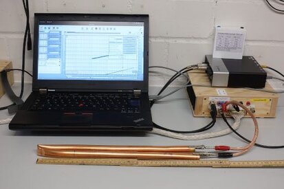
The amplifier has a fixed gain of 10.00. Line output --> amp input. Input 1 --> the point on the amp output, before Rsense, Input 2 --> right after Rsense. In my case Rsense is built in the amp housing and the two sense connections are led out with BNC sockets, as you can see. Is that clear enough?
 

Attachments

  • Kupferrohr_Impedanz1-th.jpg
    Kupferrohr_Impedanz1-th.jpg
    27.1 KB · Views: 24

brunohydra

Registered
Thread Starter
Joined
Oct 28, 2020
Posts
9
Thank you for all.
I'll search for an amplifier and a audio interface with better quality.
 
Top Bottom