convolution room correction and room curve

moedra

Member
Joined
Mar 1, 2021
Posts
140
Hi,

I can see 1/6 is less detailed but why is it desirable? Less latency? Smaller files? Why 300 Hz? Is the difference audible? I lack the theory concerning smoothing.
No need to explain everything, just point me in the right direction, unless the explanation is very basic.

In my mind 1/12 represents 1 note of the musical scale resolution, 1/6 would represent 2. I might be wrong but intuitively that's what I underdand.

I already have those books:
Sound Reproduction The Acoustics and Psychoacoustics of Loudspeakers and Rooms Floyd Toole
Master Handbook of Acoustics
THE ACOUSTICS AND PSYCHOACOUSTICS OF LOUDSPEAKERS AND ROOMS – THE STEREO PAST AND THE MULTICHANNEL FUTURE

View attachment 73415
All we are trying to do is correct for the signal while ignoring reflections, which is why we need the smoothed response to be used instead of the raw data. Since the raw data contains the reflections, we would be over-correcting if we do the calculations with it. Hence the need to bake the smoothing into the measurements. We are just trying to not over-correct, so we can get better results by smoothing the highs more than the lows. Focusing more resolution on the low end is better, because the reflections there show up in a different form and are dealt with differently.

300Hz in this case was just an example. You should put the crossover (blend) frequency wherever your room's transition zone is, so that more resolution can be used to deal with the low end, where the crests in the waves are further apart. It seems backwards, but doing it this way almost always sound better. Var smoothing is following the same principle, but it's a little too smooth in the top for me. 1/12 nails the low end for me, and I like 1/6 up top. 1/6 is more in line with how our ears hear everything without being too vague. It's really a matter of what sounds best to you.
 
Last edited:

bixite

Member
Joined
Nov 30, 2022
Posts
17
I think I will. In the meantime, here's a workaround that doesn't require editing txt files. It doesn't interpolate the values across the spectrum, but it does at least blend the two values together at a definable frequency over a very small fixed range. Unfortunately, we can't define the blend range, but at least we have something.

1 • Export the measurement at 1/12 smoothing
2 • Export the measurement again at 1/6 smoothing
3 • Import both smoothed responses
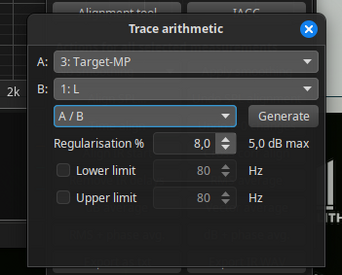
4 • Go to the arithmetic panel and merge B to A as follows with blend enabled:
- A is the smoother response, i.e. 1/6
- B is the more detailed response, i.e. 1/12
- Type in the frequency at which you want the blend to happen, then generate the result

The result of the math will leave you with a measurement with 1/12 smoothing below the blend frequency and 1/6 smoothing above it. All that remains is to generate a min phase copy of this measurement.

View attachment 73414
Great and thanks! I just tried this out and it seems that this approach can be iterated with more smoothing (e.g. 1/12 up to 200, 1/6 up to 8k, 1/3 above 8k). This works by using the "Merge B toA" result with the next smoothing.
This is much more comfortable than editing the TXT-Files and the "Blend" option automatically takes care for smooth transitions!
I notice a little variation in the SPL of the generated measurement which I do not understand.
 

linuxonly

Member
Thread Starter
Joined
Jul 27, 2024
Posts
112
More  
Preamp, Processor or Receiver
Logitech Z906
DAC
AMD FCH Azalia
Computer Audio
SPDIF output with alsa, pipewire, wireplumber on Fedora 40
Streaming Equipment
Kodi
Front Height Speakers
33 in
Middle Height Speakers
30 in
Rear Height Speakers
57 in
Video Display Device
X11/VGA + X11/DVI
All we are trying to do is correct for the signal while ignoring reflections, which is why we need the smoothed response to be used instead of the raw data. Since the raw data contains the reflections, we would be over-correcting if we do the calculations with it. Hence the need to bake the smoothing into the measurements. We are just trying to not over-correct, so we can get better results by smoothing the highs more than the lows. Focusing more resolution on the low end is better, because the reflections there show up in a different form and are dealt with differently.

300Hz in this case was just an example. You should put the crossover (blend) frequency wherever your room's transition zone is, so that more resolution can be used to deal with the low end, where the crests in the waves are further apart. It seems backwards, but doing it this way almost always sound better. Var smoothing is following the same principle, but it's a little too smooth in the top for me. 1/12 nails the low end for me, and I like 1/6 up top. 1/6 is more in line with how our ears hear everything without being too vague. It's really a matter of what sounds best to you.
Amazing. I found a detailed explanation there - https://www.digistar.cl/forum/viewtopic.php?t=794

Calculated transition zone to be 730 Hz in living room (4,22 m x 3,76 m x 2,29 m) and 790 Hz in music room (6.03 x 3.27 x 2.67m). Will experiment from that

@moedra Thanks a lot. I'm very curious about it. I can easily make A B comparisons in living room but not in stereo room where the speakers aren't in the same room as the computer, in fact they're not even on the same floor.
 

moedra

Member
Joined
Mar 1, 2021
Posts
140
Great and thanks! I just tried this out and it seems that this approach can be iterated with more smoothing (e.g. 1/12 up to 200, 1/6 up to 8k, 1/3 above 8k). This works by using the "Merge B toA" result with the next smoothing.
This is much more comfortable than editing the TXT-Files and the "Blend" option automatically takes care for smooth transitions!
I notice a little variation in the SPL of the generated measurement which I do not understand.
Yes of course! Just don't forget to generate a minimum phase copy of your final smoothed response.
 

moedra

Member
Joined
Mar 1, 2021
Posts
140
Amazing. I found a detailed explanation there - https://www.digistar.cl/forum/viewtopic.php?t=794

Calculated transition zone to be 730 Hz in living room (4,22 m x 3,76 m x 2,29 m) and 790 Hz in music room (6.03 x 3.27 x 2.67m). Will experiment from that

@moedra Thanks a lot. I'm very curious about it. I can easily make A B comparisons in living room but not in stereo room where the speakers aren't in the same room as the computer, in fact they're not even on the same floor.
Cool. Honestly, I think 1/12 smoothing over the entire range sounds amazing. If you don't notice any difference with different smoothing levels, save yourself some time and effort and just use 1/12 for everything. It's detailed enough to control the lows and smooth enough to correct the highs in a very pleasing way.
 

linuxonly

Member
Thread Starter
Joined
Jul 27, 2024
Posts
112
More  
Preamp, Processor or Receiver
Logitech Z906
DAC
AMD FCH Azalia
Computer Audio
SPDIF output with alsa, pipewire, wireplumber on Fedora 40
Streaming Equipment
Kodi
Front Height Speakers
33 in
Middle Height Speakers
30 in
Rear Height Speakers
57 in
Video Display Device
X11/VGA + X11/DVI
The audio quality is unbelievable and the procedure is very simple to follow. I have, in my mind, a quality stereo system and it never sounded like that. All controls, tone, balance, loudness are kept flat for best results. That is something I never did before.

My stereo system evolved from a custom made preamplifier build with quality op amps, a Quad 33 303 as main power amp and 2 9 cu in ft bass-reflex loudspeakers using LC crossovers, to a 6 channels individually driven speaker where the tweeter pair is driven from one amplifier, the mids from a second (the Quad 33 303) and the woofers, by another stereo amp. The loudspeakers were build in 1975 and the 15 in woofers reconed in 2000.

https://sound-au.com/project09.htm presents the 24 dB/Octave 3-Way Linkwitz Riley Crossover to place between the preamp and the 3 stereo power amps. I got rid of the LC crossovers. The Quad 33 303 being an inverting amplifier, it's outputs must be inverted (i.e. - to +). The Quad, being an over 50 years old beast, was recapped 8 years ago and a 60 Hz or 120Hz hum issue was fixed. All in all, apart from the Quad 33 303, the system was designed and build from scratch, resulting in a high performance, low budget stereo system.

It's quite an experience to listen to a bass being played and being able to hear every single note with the same intensity and coming from the same point in space.

I couldn't acheive something comparable with tone controls where the 2 crossover points could be varied all over the range as well as the gain, graphic equalizers and so on. It was better, but still far from what we're acheiving here.

I lost 15 dB in the correction process, but the system is now linear from 13 Hz to 22 kHz.

@moedra Thanks again for your hard work. You made someone very happy, and I'm sure you will continue to make many others more.

And indeed, my heartfelt thanks and kind regards to @John Mulcahy
 
Last edited:

moedra

Member
Joined
Mar 1, 2021
Posts
140
The audio quality is unbelievable and the procedure is very simple to follow. I have, in my mind, a quality stereo system and it never sounded like that. All controls, tone, balance, loudness are kept flat for best results. That is something I never did before.

My stereo system evolved from a custom made preamplifier build with quality op amps, a Quad 33 as main power amp and 2 9 cu in ported loudspeakers using LC crossovers, to a 6 channels individually driven speaker where the tweeter pair is driven from one amplifier, the mids from a second (the Quad 33) and the woofers, by another stereo amp. The loudspeakers were build in 1975 and the 15 in woofers reconed in 2000.

https://sound-au.com/project09.htm presents the 24 dB/Octave 3-Way Linkwitz Riley Crossover to place between the preamp and the 3 stereo power amps. The Quad 33 being an inverting amplifier, it's outputs must be inverted (i.e. - to +). The Quad, being an over 50 years old beast, was recapped 8 years ago and a 60 Hz or 120Hz hum issue was fixed. All in all, apart from the Quad 33, the system was designed and build from scratch, resulting in a high performance, low budget stereo system.

It's quite an experience to listen to a bass being played and being able to hear every single note with the same intensity and coming from the same point in space.

I couldn't acheive something comparable with tone controls where the 2 crossover points could be varied all over the range as well as the gain, graphic equalizers and so on. It was better, but still far ftom what we're acheiving here.

@moedra Thanks again for your hard work. You made someone very happy, and I'm sure you will continue to make many others more.
Love it. Spread the word around to anyone you know who can take advantage of it. I will begin working on a video.
 

JStewart

Senior AV Addict
Supporter
Joined
Dec 5, 2017
Posts
2,371
Location
Central FL
If anyone else has a moment to try out the procedure and let me know what your experience is, I'd appreciate it.

@moedra , I did a run though your procedure. Followed it step by step looking for anything amiss. The procedure is error free. I haven't upgraded to the latest REW version so the UI wasn't 100% the same, but that’s to be expected.

The filter's sound very good! Once again. nice piece of work! Very easy. Great results. Wish my car dsp did convolution.

I reserved a few dB headroom in Roon for the little filter boost at 250Hz. I should have dropped the target a touch more to adhere to the exact instructions.

2024-09-09.png
 

bixite

Member
Joined
Nov 30, 2022
Posts
17
... I reserved a few dB headroom in Roon for the little filter boost at 250Hz. I should have dropped the target a touch more to adhere to the exact instructions...
How did you set MaxGain in the TraceArithmetic of A/B. Since you have a boost, you probably have allowed a few db there, correct?

Did you measure, if the dip went away? When boosting you do not know in advance, if it will have an effect.
 

JStewart

Senior AV Addict
Supporter
Joined
Dec 5, 2017
Posts
2,371
Location
Central FL
How did you set MaxGain in the TraceArithmetic of A/B
I didn’t. Since the target is at or below the response everywhere but 250Hz gain is effectively unchanged or reduced. While I doubt I’d run into digital clipping at 250Hz, it just seemed good hygiene to take the gain down a couple of dB in Roon. I‘ll turn it off sometime and see if the Clipping indicator lights.


Did you measure, if the dip went away? When boosting you do not know in advance, if it will have an effect.

No and II didn’t bother measuring after because I already knew what to expect from prior experiences over the years. It’s caused by SBIR and will mitigate some, but not go away with EQ.
 

JStewart

Senior AV Addict
Supporter
Joined
Dec 5, 2017
Posts
2,371
Location
Central FL
My speakers have always sounded better to my ears by not EQing too high if I'm using min phase filters. For reasons I don't understand, Dirac and Focus Fidelity, which do impulse correction, sound better full range.
It occurred to me that instead of merging, for example, a 1/6 and 1/12 octave response, why not just merge the target with the response? Then no correction will be made whatsoever in the chosen region. In this case, above 235Hz.

Here is the original and "target merged" response. Somehow REW took care of getting the measurements relative SPL between the two correct on it's own.

2024-09-10 (1).png


And the merged responses with filters.

2024-09-10.png


This sounds better to me with my speakers and room which, I will admit, may just be because I'm more used to it.

Enough fun for now.

Edit:
 

moedra

Member
Joined
Mar 1, 2021
Posts
140
@JStewart You are probably very used to the way your speakers sound. The response seems flat enough to warrant that. Dirac has a proprietary way of handling the top frequencies. It is very odd, what it does. I can't really explain it but I have measured the filters it generates. They seem somehow phase manipulated in the top. Focus Fidelity does true time domain correction, so that is one sure-fire way to account for better full range filtered sound.

It's unclear to me how you are getting any boosting over zero on the scale in REW with your filters. Following my guide, you should not see anything reach up over 0.. If Max Gain is left at 0.0 you should have no positive amplitude adjustments. There must be a discrepancy based on your version of REW.
 

JStewart

Senior AV Addict
Supporter
Joined
Dec 5, 2017
Posts
2,371
Location
Central FL
It's unclear to me how you are getting any boosting over zero on the scale in REW with your filters. Following my guide, you should not see anything reach up over 0.. If Max Gain is left at 0.0 you should have no positive amplitude adjustments. There must be a discrepancy based on your version of REW.

When I have some more time I’ll upgrade and start over.
The trace arithmetic control panel on the version I’m using has a “regularisation” (Sp?) control and not “max gain”. Not sure what “regularisation “ does.
I also used measurements created in Impala and imported to REW. Perhaps there is some unwanted small change taking place on the impulse response import. I’ll take them in REW next time.
 

linuxonly

Member
Thread Starter
Joined
Jul 27, 2024
Posts
112
More  
Preamp, Processor or Receiver
Logitech Z906
DAC
AMD FCH Azalia
Computer Audio
SPDIF output with alsa, pipewire, wireplumber on Fedora 40
Streaming Equipment
Kodi
Front Height Speakers
33 in
Middle Height Speakers
30 in
Rear Height Speakers
57 in
Video Display Device
X11/VGA + X11/DVI
The trace arithmetic control panel on the version I’m using has a “regularisation” (Sp?) control and not “max gain”. Not sure what “regularisation “ does.
That is correct. IIRC Example of regulation that I tested a few times: 8% = 5dB max

Capture d’écran du 2024-09-11 10-12-57.png
 

Mike0815

New Member
Joined
Feb 19, 2020
Posts
31
Location
EU
More  
Other Equipment
CamillaDSP
Hello John,

I'm following moedra's howto but apply it to a 3 way speaker here for my woofer. Observing that convolution filters go only down to 60dB attenuation. This results still in audible sound in the tweeter range.
Please take a look at that screenshot. Could you make A/B filters attenuate more than 60dB or is there something I missed applying?
I could of course add some IIR low pass filtering before but it would be nicer and more convinient without.

Thanks for this great software.

Bildschirmfoto 2024-09-21 um 11.23.50.png
 

linuxonly

Member
Thread Starter
Joined
Jul 27, 2024
Posts
112
More  
Preamp, Processor or Receiver
Logitech Z906
DAC
AMD FCH Azalia
Computer Audio
SPDIF output with alsa, pipewire, wireplumber on Fedora 40
Streaming Equipment
Kodi
Front Height Speakers
33 in
Middle Height Speakers
30 in
Rear Height Speakers
57 in
Video Display Device
X11/VGA + X11/DVI
I tried to prepare the traces, I have 6, not 2, before applying @moedra 's method. Is it overkill? It sounds differently, very subtle. I can't decide which is best.

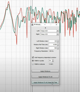
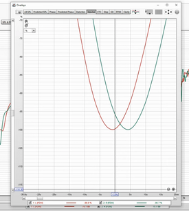
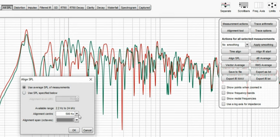
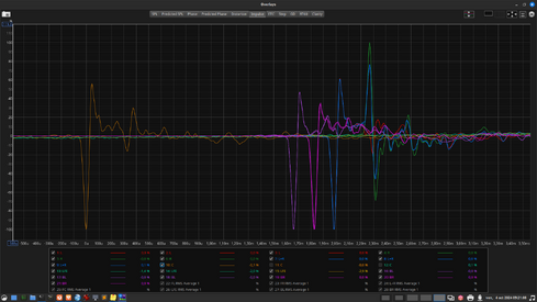
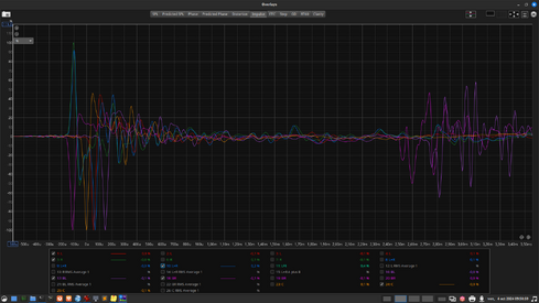
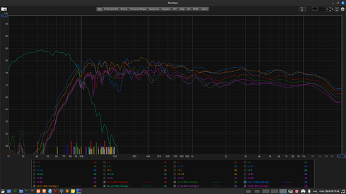
I first windowed the traces, then time aligned, and lastly SPL aligned at 500Hz. Then I followed the recommended procedure and generaed new filters. With CamillaDSP, I can switch at the press of a button. 1.png 2.png 3.png 4.png
 

moedra

Member
Joined
Mar 1, 2021
Posts
140
I tried to prepare the traces, I have 6, not 2, before applying @moedra 's method. Is it overkill? It sounds differently, very subtle. I can't decide which is best.

I first windowed the traces, then time aligned, and lastly SPL aligned at 500Hz. Then I followed the recommended procedure and generaed new filters. With CamillaDSP, I can switch at the press of a button. View attachment 74224 View attachment 74225 View attachment 74226 View attachment 74227
The problem with FDW in Room EQ Wizard is that it is applied without a psychoacoustic treatment ahead of it. This may be appropriate in certain situations but if the goal is to generate perceptually accurate acoustic correction, you have to apply a psychoacoustic treatment to the response ahead of the FDW. I studied how Acourate does this, but REW doesn't have an equivalent feature that I'm aware of. If you don't treat the response first, the FDW will include the deep dips that I can see in your graphs, which is not what we want. I got around that by simply smoothing the data to 1/12 and leaving FDW out of the recipe, which yields a result much closer to that treated FDW response that I see in Acourate's macro 1. Of course, in REW you have to bake that smoothing into the measurement, which is why I export the smoothed measurements as txt files, bring them back into the session, and process them instead of the original measured responses. REW seems to ignore smoothing settings (they are likely just visual filters) when it performs the necessary calculations, so you can't just smooth the original measurements for processing. I tried that for a long time before figuring all of this out. You need the smoothed txt imports for the math. The procedure I wrote in that guide essentially emulates what Acourate does in macros 1, 2, and 3, but without the need for FDW.

I don't think you needed to align SPL either, as this will surely cause the L/R balance to be thrown off slightly in the filter. Why do you have six measurements? Yes, I think it's overkill.
 
Last edited:

linuxonly

Member
Thread Starter
Joined
Jul 27, 2024
Posts
112
More  
Preamp, Processor or Receiver
Logitech Z906
DAC
AMD FCH Azalia
Computer Audio
SPDIF output with alsa, pipewire, wireplumber on Fedora 40
Streaming Equipment
Kodi
Front Height Speakers
33 in
Middle Height Speakers
30 in
Rear Height Speakers
57 in
Video Display Device
X11/VGA + X11/DVI
The problem with FDW in Room EQ Wizard is that it is applied without a psychoacoustic treatment ahead of it. This may be appropriate in certain situations but if the goal is to generate perceptually accurate acoustic correction, you have to apply a psychoacoustic treatment to the response ahead of the FDW. I studied how Acourate does this, but REW doesn't have an equivalent feature that I'm aware of. If you don't treat the response first, the FDW will ignore the deep dips that I can see in your graphs. I got around that by simply smoothing the data to 1/12 and leaving FDW out of the recipe, which yields a result much closer to that treated FDW response that I see in Acourate's macro 1. Of course, in REW you have to bake that smoothing into the measurement, which is why I export the smoothed measurements as txt files, bring them back into the session, and process them instead of the original measured responses. REW seems to ignore smoothing settings (they are likely just visual filters) when it performs the necessary calculations, so you can't just smooth the original measurements for processing. I tried that for a long time before figuring all of this out. You need the smoothed txt imports for the math. The procedure I wrote in that guide essentially emulates what Acourate does in macros 1, 2, and 3, but without the need for FDW.
Thanks for the detailed explanation. Totally makes sense.
I don't think you needed to align SPL either, as this will surely cause the L/R balance to be thrown off slightly in the filter. Why do you have six measurements? Yes, I think it's overkill.
It's my home theatre. 6 channels. For my stereo I didn't bother.
 

moedra

Member
Joined
Mar 1, 2021
Posts
140
Thanks for the detailed explanation. Totally makes sense.

It's my home theatre. 6 channels. For my stereo I didn't bother.
My response featured a typo, which I have fixed. It said that FDW will ignore the dips. What I meant to say was that the FDW will not ignore the dips. We don't want those dips included in the FDW calculations. Acourate's psychoacoustic treatment removes them prior to applying FDW. The only way to mimic that result (while retaining accuracy) with REW is to use the exported/imported responses with the smoothing baked into them. Therefore, applying FDW with REW for our purpose is unnecessary.
 
Last edited:

linuxonly

Member
Thread Starter
Joined
Jul 27, 2024
Posts
112
More  
Preamp, Processor or Receiver
Logitech Z906
DAC
AMD FCH Azalia
Computer Audio
SPDIF output with alsa, pipewire, wireplumber on Fedora 40
Streaming Equipment
Kodi
Front Height Speakers
33 in
Middle Height Speakers
30 in
Rear Height Speakers
57 in
Video Display Device
X11/VGA + X11/DVI
My response featured a typo, which I have fixed. It said that FDW will ignore the dips. What I meant to say was that the FDW will not ignore the dips. We don't want those dips included in the FDW calculations. Acourate's psychoacoustic treatment removes them prior to applying FDW. The only way to mimic that result (while retaining accuracy) with REW is to use the exported/imported responses with the smoothing baked into them. Therefore, applying FDW with REW for our purpose is unnecessary.
Correct. Taking note. You've already mentioned it. I didn't had it in mind while experimenting to get all the speakers to fire simulteneously. It's rarely a problem with stereo because it's easy to set an equidistant MLP to each speaker, but with a surround system, it's more challenging.

Using your method, and remeasuring wth the filters on gives a dispersed impulse response.

meridian impulse.png


What I'm trying to do is to get all the speakers to fire delayed by using the delays from that measurements and set them as offsets in the DSP. Here I took a set of measurements and due to minor difference in the mic position, the impulses that should normally be all at t=0 are within plus or minus 150 uSec. Is it something desirable to want to see all the speakers to fire simultaneouly from the MLP perspective?

test2 impulse.png

Here's the corrected response I get BTW,

meridian spl.png
 
Last edited:

linuxonly

Member
Thread Starter
Joined
Jul 27, 2024
Posts
112
More  
Preamp, Processor or Receiver
Logitech Z906
DAC
AMD FCH Azalia
Computer Audio
SPDIF output with alsa, pipewire, wireplumber on Fedora 40
Streaming Equipment
Kodi
Front Height Speakers
33 in
Middle Height Speakers
30 in
Rear Height Speakers
57 in
Video Display Device
X11/VGA + X11/DVI
You're still boosting during the inversion, which is giving you approximately 7 or 8 decibels of boost above 0dB around 2600Hz. The region between 2000Hz and 4500Hz is boosted. There's a little boosting above 0dB at 1kHz as well. When you do the inversion, leave the boost amount (max gain) at 0.0 like I have in the picture. This is somewhat vital to avoid potential problems clipping the output of the convolver running the filter. Look at mine again. There's nothing going over zero.
Neglected this too long and installed REW beta. The current 5.31.3 is unable to do that. Regenerated only the Inv curves and exported as wav
 

linuxonly

Member
Thread Starter
Joined
Jul 27, 2024
Posts
112
More  
Preamp, Processor or Receiver
Logitech Z906
DAC
AMD FCH Azalia
Computer Audio
SPDIF output with alsa, pipewire, wireplumber on Fedora 40
Streaming Equipment
Kodi
Front Height Speakers
33 in
Middle Height Speakers
30 in
Rear Height Speakers
57 in
Video Display Device
X11/VGA + X11/DVI
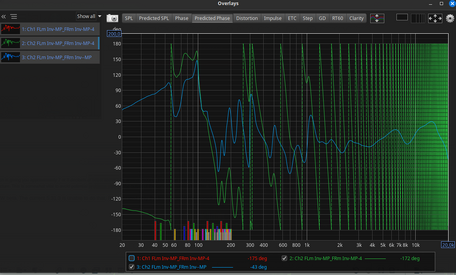
A question. I've been wondering for quite a time what exporting IR to wav with minimum phase ticked was doing precisely. I do understand they are audio files and as such do not content phase information like text files would.

Being curious, I imported one of my IR wav filters in REW as audio data and clearly they're not minimal phase.

2 (green) is the right channel imported wav phase; 3 (blue) is a minimum phase copy I created of it in REW
 

Attachments

  • Capture d’écran du 2024-10-27 12-53-13.png
    Capture d’écran du 2024-10-27 12-53-13.png
    282.2 KB · Views: 11

John Mulcahy

REW Author
Joined
Apr 3, 2017
Posts
8,052
I've been wondering for quite a time what exporting IR to wav with minimum phase ticked was doing precisely.
It export the IR of the minimum phase response generated from the system's magnitude response.

When you import an IR you need to make sure t=0 is set appropriately to see the correct phase response, otherwise the phase will include a time delay.
 
Top Bottom