Measuring my DIY Speakers for Crossover Design

Nordo

Member
Thread Starter
Joined
Oct 7, 2019
Posts
137
More  
Preamp, Processor or Receiver
Denon AVR X1500H
Additional Amp
Sub amp - Behringer EP2500
Universal / Blu-ray / CD Player
Panasoic BD35
Front Speakers
DIY
Center Channel Speaker
DIY
Surround Speakers
DIY
Surround Back Speakers
DIY
Front Height Speakers
-
Rear Height Speakers
-
Subwoofers
Four 15" infinite baffle drivers
Other Speakers
HTPC (windows 10 with Kodi)
Screen
Matt white "blockout" curtain liner
Video Display Device
Epson EMP-TW2000 projector
Not sure if I have a problem with my Impedance Measurements.
I built my testing rig which included a 100ohm resistor.
I had to run the inputs and output through a UCA222 "audio interface with digital output", which connects vis a single USB port.
I use ASIO audio drivers.
I had the level as high as a could without clipping, but I was still getting messages saying that my signal was low and I shoild increase the input level.
My problem is that I don't know how to do that.
BTW, I did get a result curve that is approximately what I was expecting.
Any ideas?
 

John Mulcahy

REW Author
Joined
Apr 3, 2017
Posts
8,174
For an impedance measurement the level check is only done on the reference channel, which should be getting a direct loopback from the output. Have you selected the correct input channel?
 

Nordo

Member
Thread Starter
Joined
Oct 7, 2019
Posts
137
More  
Preamp, Processor or Receiver
Denon AVR X1500H
Additional Amp
Sub amp - Behringer EP2500
Universal / Blu-ray / CD Player
Panasoic BD35
Front Speakers
DIY
Center Channel Speaker
DIY
Surround Speakers
DIY
Surround Back Speakers
DIY
Front Height Speakers
-
Rear Height Speakers
-
Subwoofers
Four 15" infinite baffle drivers
Other Speakers
HTPC (windows 10 with Kodi)
Screen
Matt white "blockout" curtain liner
Video Display Device
Epson EMP-TW2000 projector
For an impedance measurement the level check is only done on the reference channel, which should be getting a direct loopback from the output. Have you selected the correct input channel?
Thanks John, I'm pretty sure everything is connected correctly, but I'll check.
When using a USB 3.0 for connection, ASIO gives rather vague names for the channels, which makes it harder to check.

EDIT - checked again. Think I had a loose connection somewhere. :rubeyes:
Also I found that by Checking Levels, I confirmed which ASIO channel was feeding which speaker - my test speaker or my reference speaker.
 
Last edited:

Nordo

Member
Thread Starter
Joined
Oct 7, 2019
Posts
137
More  
Preamp, Processor or Receiver
Denon AVR X1500H
Additional Amp
Sub amp - Behringer EP2500
Universal / Blu-ray / CD Player
Panasoic BD35
Front Speakers
DIY
Center Channel Speaker
DIY
Surround Speakers
DIY
Surround Back Speakers
DIY
Front Height Speakers
-
Rear Height Speakers
-
Subwoofers
Four 15" infinite baffle drivers
Other Speakers
HTPC (windows 10 with Kodi)
Screen
Matt white "blockout" curtain liner
Video Display Device
Epson EMP-TW2000 projector
I now have another problem.:sad:
In the measurements of my woofer (RS225-8), I have a spike at around 3ms in the Impulse.
Not sure why I have a reflection so close.
So I apply a window to around 2.5ms (to catch the start of the spike).
When I apply the window, then look at my SPL, the remaining curve has been smoothened to around 1/6 smoothing.
I don't really want that amount of smoothing.
Is there anything I can do to not induce the smoothing?
BTW, ETC smotthing is set to zero.
 

dcibel

Member
Joined
Sep 10, 2017
Posts
310
I now have another problem.:sad:
In the measurements of my woofer (RS225-8), I have a spike at around 3ms in the Impulse.
Not sure why I have a reflection so close.
The obvious questions, how far is mic from speaker, speaker to floor/ceiling, etc.

When using acoustic reference, it's important to not select output L+R. You do output L, reference R, or output R, reference L, never both.

So I apply a window to around 2.5ms (to catch the start of the spike).
When I apply the window, then look at my SPL, the remaining curve has been smoothened to around 1/6 smoothing.
I don't really want that amount of smoothing.
Is there anything I can do to not induce the smoothing?
BTW, ETC smotthing is set to zero.

The window not only sets the lowest frequency captured, but also the resolution of the measurement. Using 2.5ms window as an example, the lowest frequency measured would be 400Hz, which is also the resolution of the measurement, meaning the next measured frequency through the window is at 800Hz, then 1200Hz, then 1600Hz and so on. Not great resolution.

Aim for at least 4ms window, which is possible indoors, 8ft ceiling, speaker and mic at 4ft height and mic is 1m away. You can find this "frequency resolution" value in REW in the IR Windows section.
 
Last edited:

Nordo

Member
Thread Starter
Joined
Oct 7, 2019
Posts
137
More  
Preamp, Processor or Receiver
Denon AVR X1500H
Additional Amp
Sub amp - Behringer EP2500
Universal / Blu-ray / CD Player
Panasoic BD35
Front Speakers
DIY
Center Channel Speaker
DIY
Surround Speakers
DIY
Surround Back Speakers
DIY
Front Height Speakers
-
Rear Height Speakers
-
Subwoofers
Four 15" infinite baffle drivers
Other Speakers
HTPC (windows 10 with Kodi)
Screen
Matt white "blockout" curtain liner
Video Display Device
Epson EMP-TW2000 projector
The obvious questions, how far is mic from speaker, speaker to floor/ceiling, etc.
When using acoustic reference, it's important to not select output L+R. You do output L, reference R, or output R, reference L, never both.
Thanks (yet again).
It's obvious that this is the first time I have used REW this way.
I'll set up and do the measurements again, but I'm fairly sure I had Output R as the speaker being measured, and Reference L for the reference speaker.

The measurements were taken outdoors with the speaker (and ref speaker) facing a downhill slope with no obvious reflective objects in front of the speaker within 30m.
The mic was 2000mm away at a height midway between the two cone speakers (2.5" & 8"), which was approx 1000mm above the ground.
The only possible near reflective objects were the house's roof eave - which was approx 1100mm above and slightly behind the two drivers; and maybe the brickwork above the garage door- which was approx 600mm behind the baffle face.
The idea of measuring in an ourdoor setting, was to hopefully eliminate the hassle of impulse windowing and subsequent merging.
Looks like my "ideal" measurement location wasn't so perfect after all.
If I re-measure again, I'll probably set up inside - either the double garage, or the fairly large living room.

The window not only sets the lowest frequency captured, but also the resolution of the measurement. Using 2.5ms window as an example, the lowest frequency measured would be 400Hz, which is also the resolution of the measurement, meaning the next measured frequency through the window is at 800Hz, then 1200Hz, then 1600Hz and so on. Not great resolution.

Aim for at least 4ms window, which is possible indoors, 8ft ceiling, speaker and mic at 4ft height and mic is 1m away. You can find this "frequency resolution" value in REW in the IR Windows section.
Aha - makes sense. I didn't realise that.
 

dcibel

Member
Joined
Sep 10, 2017
Posts
310
The mic was 2000mm away at a height midway between the two cone speakers (2.5" & 8"), which was approx 1000mm above the ground.
I'd like to introduce you to your driveway.
56396


2m mic distance is not necessary, it needs to be only far enough to be sufficiently "far field" to capture diffraction effects of your cabinet. I would recommend using a distance of 1m or 3x the cabinet width, whichever is furthest. Moving the mic closer to the speaker increases the window length possibilities.
56397
 

Nordo

Member
Thread Starter
Joined
Oct 7, 2019
Posts
137
More  
Preamp, Processor or Receiver
Denon AVR X1500H
Additional Amp
Sub amp - Behringer EP2500
Universal / Blu-ray / CD Player
Panasoic BD35
Front Speakers
DIY
Center Channel Speaker
DIY
Surround Speakers
DIY
Surround Back Speakers
DIY
Front Height Speakers
-
Rear Height Speakers
-
Subwoofers
Four 15" infinite baffle drivers
Other Speakers
HTPC (windows 10 with Kodi)
Screen
Matt white "blockout" curtain liner
Video Display Device
Epson EMP-TW2000 projector
I'd like to introduce you to your driveway.
View attachment 56396

2m mic distance is not necessary, it needs to be only far enough to be sufficiently "far field" to capture diffraction effects of your cabinet. I would recommend using a distance of 1m or 3x the cabinet width, whichever is furthest. Moving the mic closer to the speaker increases the window length possibilities.
View attachment 56397
My baffle width is 251mm, so 1m should be fine. My logic says it would also allow me to reduce the gain on the USB mic, which would reduce the effect of the reflections (?).

I've seen this little calculation window before. But I couldn't make sense of it.
e.g. for the 2000mm location of the mic, the path of the floor reflection is 2828mm (2.828m).
Divide by 344m/sec, and multiple by 1000 (if using 2.828m) = 8.22ms.
And I also don't understand how the shorter reflection path (mic at 1000mm), gives a Time Window of 3.59ms.
 

dcibel

Member
Joined
Sep 10, 2017
Posts
310
My baffle width is 251mm, so 1m should be fine. My logic says it would also allow me to reduce the gain on the USB mic, which would reduce the effect of the reflections (?).

Mic gain has nothing to do with reflections.

I've seen this little calculation window before. But I couldn't make sense of it.
e.g. for the 2000mm location of the mic, the path of the floor reflection is 2828mm (2.828m).
Divide by 344m/sec, and multiple by 1000 (if using 2.828m) = 8.22ms.
And I also don't understand how the shorter reflection path (mic at 1000mm), gives a Time Window of 3.59ms.
That is a wrong calculation. Subtract your 2m mic distance from 2.828m = 0.828m. Same math from here gives 2.41ms window
 

Nordo

Member
Thread Starter
Joined
Oct 7, 2019
Posts
137
More  
Preamp, Processor or Receiver
Denon AVR X1500H
Additional Amp
Sub amp - Behringer EP2500
Universal / Blu-ray / CD Player
Panasoic BD35
Front Speakers
DIY
Center Channel Speaker
DIY
Surround Speakers
DIY
Surround Back Speakers
DIY
Front Height Speakers
-
Rear Height Speakers
-
Subwoofers
Four 15" infinite baffle drivers
Other Speakers
HTPC (windows 10 with Kodi)
Screen
Matt white "blockout" curtain liner
Video Display Device
Epson EMP-TW2000 projector
That is a wrong calculation. Subtract your 2m mic distance from 2.828m = 0.828m. Same math from here gives 2.41ms window
Now I see :T
It's the difference between the Impulse's direct signal and the first reflected signal.

As I said somewhere else, I learn a little bit more each day - thanks.
 

Nordo

Member
Thread Starter
Joined
Oct 7, 2019
Posts
137
More  
Preamp, Processor or Receiver
Denon AVR X1500H
Additional Amp
Sub amp - Behringer EP2500
Universal / Blu-ray / CD Player
Panasoic BD35
Front Speakers
DIY
Center Channel Speaker
DIY
Surround Speakers
DIY
Surround Back Speakers
DIY
Front Height Speakers
-
Rear Height Speakers
-
Subwoofers
Four 15" infinite baffle drivers
Other Speakers
HTPC (windows 10 with Kodi)
Screen
Matt white "blockout" curtain liner
Video Display Device
Epson EMP-TW2000 projector
I wonder if someone can help or explain why I'm getting very early reflections showing up in my Impulse Graph.
I've attached the mdat of my TL woofer (Dayton RS225-8) for the on axis measurement.
The other driver (a Vifa TC9FD-8) also has some very early spikes.
Adjusting for the 1m distance from driver to mic, my first reflections should have been :-
3.4ms - Floor (covered with thick fibreglass batts)
6.6ms - Ceiling (a doona hung horizontally from the plasterboard/drywall)
14ms - Side Walls and wall facing speaker (plasterboard/drywall)

But there is a spike at 0.5ms, and another at 1.2ms; and very little at the expected times noted above.
The ETC seems to confirm these spikes, as well as a smaller one at 11.7ms (which could be a cupboard against one of the side walls).

For designing my crossover, I should window out first reflections and merge near field measurements with what would be left of my 1m measurements.
But such a small window would take virtually all the information out of the 1m measurements.

Can anyone see what's happening? Or if I'm worrying over nothing?
 

Attachments

  • RS225 hor 0.mdat
    639 KB · Views: 44

dcibel

Member
Joined
Sep 10, 2017
Posts
310
Given the discussion of acoustic timing reference, the only flag is that the woofer impulse occurs before t=0. What is the acoustic timing reference and where is it in relation to the mic? Acoustic reference can (probably should) be located relatively close to the mic.

The rest looks like your bell is ringing. RS225 is a metal cone.
 

skid00

Member
Joined
Mar 20, 2020
Posts
127
More  
Main Amp
2 x Adcom GFA 555
Front Speakers
Carver Amazing Platinum Mark IV
I've used fiberglass taped to the tripod legs, and the impulses were less cluttered.

My last measurements just used a 1 foot square, 3 inch thick block of soft open-cell foam, with the mic pushed thru the foam. This made a large difference to early reflections.
 

Nordo

Member
Thread Starter
Joined
Oct 7, 2019
Posts
137
More  
Preamp, Processor or Receiver
Denon AVR X1500H
Additional Amp
Sub amp - Behringer EP2500
Universal / Blu-ray / CD Player
Panasoic BD35
Front Speakers
DIY
Center Channel Speaker
DIY
Surround Speakers
DIY
Surround Back Speakers
DIY
Front Height Speakers
-
Rear Height Speakers
-
Subwoofers
Four 15" infinite baffle drivers
Other Speakers
HTPC (windows 10 with Kodi)
Screen
Matt white "blockout" curtain liner
Video Display Device
Epson EMP-TW2000 projector
Given the discussion of acoustic timing reference, the only flag is that the woofer impulse occurs before t=0. What is the acoustic timing reference and where is it in relation to the mic? Acoustic reference can (probably should) be located relatively close to the mic.

The rest looks like your bell is ringing. RS225 is a metal cone.
The acoustic reference speaker was level with the Mic, close to the test speaker, and slightly behind.
The recorded timing offset was -0.2734ms (-94mm) which would be correct.

I set t=0 to where the impulse starts to rise above the noise floor.
 

Nordo

Member
Thread Starter
Joined
Oct 7, 2019
Posts
137
More  
Preamp, Processor or Receiver
Denon AVR X1500H
Additional Amp
Sub amp - Behringer EP2500
Universal / Blu-ray / CD Player
Panasoic BD35
Front Speakers
DIY
Center Channel Speaker
DIY
Surround Speakers
DIY
Surround Back Speakers
DIY
Front Height Speakers
-
Rear Height Speakers
-
Subwoofers
Four 15" infinite baffle drivers
Other Speakers
HTPC (windows 10 with Kodi)
Screen
Matt white "blockout" curtain liner
Video Display Device
Epson EMP-TW2000 projector
How is the mic supported? You can get reflections from the mic holder, the stand, ...
I used a cheap boom mic stand, with the stand off to the side.
The boom and mic stand were the only things in front of the test speaker before a drywall timber framed wall at approx 3400mm (11'), although the wall had a laundry tub, which would have been approx 3000mm (9'10") from the test speaker.

The "test room" was a double garage - 6000mm x 7000mm (19'8" x 23'0") with the test speaker located in the middle.
 

Nordo

Member
Thread Starter
Joined
Oct 7, 2019
Posts
137
More  
Preamp, Processor or Receiver
Denon AVR X1500H
Additional Amp
Sub amp - Behringer EP2500
Universal / Blu-ray / CD Player
Panasoic BD35
Front Speakers
DIY
Center Channel Speaker
DIY
Surround Speakers
DIY
Surround Back Speakers
DIY
Front Height Speakers
-
Rear Height Speakers
-
Subwoofers
Four 15" infinite baffle drivers
Other Speakers
HTPC (windows 10 with Kodi)
Screen
Matt white "blockout" curtain liner
Video Display Device
Epson EMP-TW2000 projector
I've used fiberglass taped to the tripod legs, and the impulses were less cluttered.

My last measurements just used a 1 foot square, 3 inch thick block of soft open-cell foam, with the mic pushed thru the foam. This made a large difference to early reflections.
The first tests I ever did, approx 30 years ago, was in an open paddock with a SPL meter on a tripod.
I also wrapped the tripod legs in a big thick feather doona.

The Mic surrounded by acoustic material sounds like an interesting approach.
But I think most acoustic materials would reflect some frequencies, albeit only very high frequencies. Not sure how that would effect the impulse.
 

Nordo

Member
Thread Starter
Joined
Oct 7, 2019
Posts
137
More  
Preamp, Processor or Receiver
Denon AVR X1500H
Additional Amp
Sub amp - Behringer EP2500
Universal / Blu-ray / CD Player
Panasoic BD35
Front Speakers
DIY
Center Channel Speaker
DIY
Surround Speakers
DIY
Surround Back Speakers
DIY
Front Height Speakers
-
Rear Height Speakers
-
Subwoofers
Four 15" infinite baffle drivers
Other Speakers
HTPC (windows 10 with Kodi)
Screen
Matt white "blockout" curtain liner
Video Display Device
Epson EMP-TW2000 projector
Still can't figure out what's happening with my measurements.
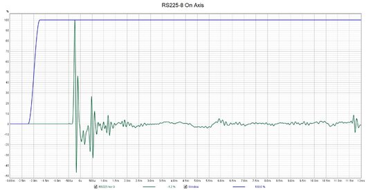
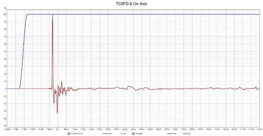
I have added seperate screen shots of my on-axis Impulses of my two drivers (7" RS225 and 2.5" TC9FD).
If the early spikes I was seeing in the RS225 Impulse were due to early reflections off something, I should see them in the TC9FD Impulse, as nothing changed apart from sending the signals to the other driver.
But the early spikes are not in the TC9FD's Impulse.
Perhaps there is something to the "ringing" theory that decibel put forward?

Can anyone help? RS225-8 On Axis.jpg TC9FD-8 On Axis.jpg
I really want to move forward with the project (and stop pestering everyone).
57053
57054
 

dcibel

Member
Joined
Sep 10, 2017
Posts
310
Perhaps there is something to the "ringing" theory that decibel put forward?
Could be....:rolleyes:

Nothing to see here, for more information refer to your frequency response result. Your measurement is fine. If you want clear indication of reflections, use a tweeter, high frequency energy for pronounced short duration spikes.
 

Nordo

Member
Thread Starter
Joined
Oct 7, 2019
Posts
137
More  
Preamp, Processor or Receiver
Denon AVR X1500H
Additional Amp
Sub amp - Behringer EP2500
Universal / Blu-ray / CD Player
Panasoic BD35
Front Speakers
DIY
Center Channel Speaker
DIY
Surround Speakers
DIY
Surround Back Speakers
DIY
Front Height Speakers
-
Rear Height Speakers
-
Subwoofers
Four 15" infinite baffle drivers
Other Speakers
HTPC (windows 10 with Kodi)
Screen
Matt white "blockout" curtain liner
Video Display Device
Epson EMP-TW2000 projector
Could be....:rolleyes:

Nothing to see here, for more information refer to your frequency response result. Your measurement is fine. If you want clear indication of reflections, use a tweeter, high frequency energy for pronounced short duration spikes.
Thanks again.
Maybe the cone touches the phase plug at some point?
Not sure what to look for in the FR graphs when checking for the effect of early reflections in my measurements.
The test speaker doesn't have a tweeter.
Maybe I'm making a mountain out of a mole hill. But that's what I want someone to confirm.:sarcastic:
 

Nordo

Member
Thread Starter
Joined
Oct 7, 2019
Posts
137
More  
Preamp, Processor or Receiver
Denon AVR X1500H
Additional Amp
Sub amp - Behringer EP2500
Universal / Blu-ray / CD Player
Panasoic BD35
Front Speakers
DIY
Center Channel Speaker
DIY
Surround Speakers
DIY
Surround Back Speakers
DIY
Front Height Speakers
-
Rear Height Speakers
-
Subwoofers
Four 15" infinite baffle drivers
Other Speakers
HTPC (windows 10 with Kodi)
Screen
Matt white "blockout" curtain liner
Video Display Device
Epson EMP-TW2000 projector
The more I learn, the more confused I become.

As I am using a UMIK-1 usb mic, I will be using acoustic reference timing.
I understand that in the Measurement window, I need to add the necessary adjustment in the Timing Offset window. In my case, the difference in distance between the reference signal speaker and the speaker under test.

But I need to know what settings I should be using in the Preferences/Analysis window when measuring speakers?
Any help would be appreciated.
I've already had to throw out two full sets of 180deg measurements due to not fully understanding settings such as timing and delays.
 

dcibel

Member
Joined
Sep 10, 2017
Posts
310
Problem with previous measurements was primarily where you located the mic, not the software settings.
 

dcibel

Member
Joined
Sep 10, 2017
Posts
310
That guide is fine for complete speakers, however for individual drivers for design purpose, timing reference needs to be included to combine the measurements of multiple drivers. There’s a perfectly good guide written by the VituixCAD developer here, Nordo just needs to figure out the difference between acoustic timing reference and loopback reference so he can follow the guide using his USB mic.
 

Nordo

Member
Thread Starter
Joined
Oct 7, 2019
Posts
137
More  
Preamp, Processor or Receiver
Denon AVR X1500H
Additional Amp
Sub amp - Behringer EP2500
Universal / Blu-ray / CD Player
Panasoic BD35
Front Speakers
DIY
Center Channel Speaker
DIY
Surround Speakers
DIY
Surround Back Speakers
DIY
Front Height Speakers
-
Rear Height Speakers
-
Subwoofers
Four 15" infinite baffle drivers
Other Speakers
HTPC (windows 10 with Kodi)
Screen
Matt white "blockout" curtain liner
Video Display Device
Epson EMP-TW2000 projector
Not sure if you have already come across it but there is a good guide to speaker measurements here.
That's great.
Thanks John.
I've read everything I could find relating to acoustic timing reference that you have written, but didn't come across that one.
 
Top Bottom