The same thing happens when using loopback. Previously, I only took measurements with the loopback. Then I assumed that with acoustic synchronization, the measurements would become stable. But it turned out to be almost the same. It happens that each new measurement occurs with a displacement, but sometimes it happens 5-7 in a row as it should be, that is, without displacement.


-
AUDIO VIDEO PROCESSING, SETUP & ENVIRONMENTOfficial REW (Room EQ Wizard) Support Forum Audiolense User Forum Calibration Equipment Auto-EQ Platforms / Immersive Audio Codecs Video Display Technologies / Calibration AV System Setup and Support Listening Room / Home Theater Build Projects Room Acoustics and Treatments AV Showcase Movies / Music / TV / Streaming
-
AUDIO VIDEO DISCUSSION / EQUIPMENTHome Theater / Audio and Video - Misc Topics Essence For Hi Res Audio AV Equipment Advice and Pricing Awesome Deals and Budget AV Equipment AV Receivers / Processors / Amps UHD / Blu-ray / CD Players / Streaming Devices Two Channel Hi-Fi Equipment DIY Audio Projects Computer Systems - HTPC / Gaming HD and UHD Flat Screen Displays Projectors and Projection Screens AV Accessories Buy - Sell - Trade
Navigation
Install the app
How to install the app on iOS
Follow along with the video below to see how to install our site as a web app on your home screen.
Note: This feature may not be available in some browsers.
More options
You are using an out of date browser. It may not display this or other websites correctly.
You should upgrade or use an alternative browser.
You should upgrade or use an alternative browser.
Setting t=0
- Thread starter sm52
- Start date

jtalden
Senior Member
More
- Preamp, Processor or Receiver
- Marantz AV7705 Pre/Pro
- Main Amp
- VTV 6 chnl NC252MP P-amp x 2
- Additional Amp
- Behringer DCX2496 x 2
- Universal / Blu-ray / CD Player
- OPPO BDP-103 Universal Player
- Front Speakers
- DIY SEAS H1456/H1212 Spkr x 5
- Subwoofers
- DIY JBL 2235H 15" SW x 2
- Screen
- Da-Lite Da-Snap 39105V - 92"
- Video Display Device
- Canon Home Cinema LS11000
Have you tried the suggestions about optimizing the PC for sound applications?
I think I was having problem also prior to making some PC changes years ago.
Here is one site I just quickly found. I think the advice I found was at the Focusrite website. Possibly most audio interface companies offer some advice. I think turning off wifi was some help to me, but it may have been a combination of things. Do a search and try some of the ideas offered.
Found another: Here
jtalden
Senior Member
More
- Preamp, Processor or Receiver
- Marantz AV7705 Pre/Pro
- Main Amp
- VTV 6 chnl NC252MP P-amp x 2
- Additional Amp
- Behringer DCX2496 x 2
- Universal / Blu-ray / CD Player
- OPPO BDP-103 Universal Player
- Front Speakers
- DIY SEAS H1456/H1212 Spkr x 5
- Subwoofers
- DIY JBL 2235H 15" SW x 2
- Screen
- Da-Lite Da-Snap 39105V - 92"
- Video Display Device
- Canon Home Cinema LS11000
I just remembered that I discovered that moving the mouse quickly during a measurement causes problems for me. I don't do that any more.
I read the information on your link. I know about everything that is said there. Thank you. The only thing I disagree with is to turn on the maximum and minimum states of the processor to 100. At this value, the fan is making noise almost constantly. Almost at maximum speed. Therefore, it is necessary to set the maximum state of the processor to 95 or 90 or 85, depending on the hardware. Then the processor does not overheat, and the fan always runs below the average speed, or at the minimum.
In my case, if no one tells me how to solve my problem, I will try another audio interface. Or another amplifier.
In my case, if no one tells me how to solve my problem, I will try another audio interface. Or another amplifier.
jtalden
Senior Member
More
- Preamp, Processor or Receiver
- Marantz AV7705 Pre/Pro
- Main Amp
- VTV 6 chnl NC252MP P-amp x 2
- Additional Amp
- Behringer DCX2496 x 2
- Universal / Blu-ray / CD Player
- OPPO BDP-103 Universal Player
- Front Speakers
- DIY SEAS H1456/H1212 Spkr x 5
- Subwoofers
- DIY JBL 2235H 15" SW x 2
- Screen
- Da-Lite Da-Snap 39105V - 92"
- Video Display Device
- Canon Home Cinema LS11000
So, you actually tried not moving your mouse during the measurements as well as all the other PC setup suggestions on the internet?
You now think the problem is with the amp or the audio interface. I don't see how that could be.
You now think the problem is with the amp or the audio interface. I don't see how that could be.
Sure. And I never tried. And all the recommendations were known to me.you actually tried not moving your mouse during the measurements
When you seem to have checked everything and tried it, you start to believe in anything.You now think the problem is with the amp or the audio interface. I don't see how that could be.
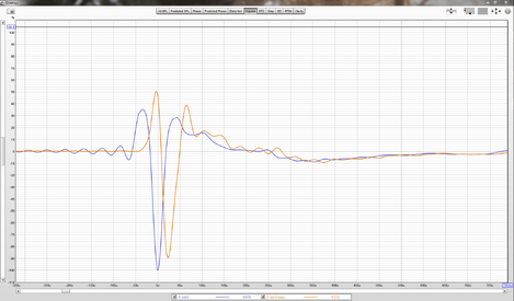
In the latest versions of REW, the impulse response changes from a change in position t = 0. An example in the screenshot. I made a copy of the measurement and shifted t = 0 on the copy. This is one question.The impulse response is never changed, all that is being done is to pick a point along the time axis and define that point as zero time.
Second question, REW for defaults set t = 0 at the first maximum IR peak. This is correct if all drivers in the speaker are connected with positive polarity. And if the polarity is not inverted when measured at the input.
If the input polarity is reversed due to the microphone or microphone preamp, or the wires in the connectors are not properly soldered, then REW correctly sets t = 0 to the first maximum peak, 'negative'. The user must click the 'Invert' button to see the real picture.
But, there are some speakers in which several drivers are connected with reverse polarity. I have so. In the attached measurement and screenshot there is such a speaker. In this case, it is correct to set t = 0 on the first positive peak. Question.
Can REW detect this by default? If not, is it possible to add a button, the activation of which will tell REW that the speaker is being measured, for which t = 0 should be set to the first positive peak, and the second negative and bigger to be ignored?
Attachments
John Mulcahy
REW Author
- Joined
- Apr 3, 2017
- Posts
- 9,254
If the option to set t=0 at the IR peak is selected when not using a timing reference t=0 will be placed at the maximum magnitude. When a timing reference is used the position of t=0 depends on the time at which the reference is detected.
You can set t=0 wherever you like using the controls provided. The 'correct' position for t=0 can depend somewhat on the DAC reconstruction filter, but in the absence of acausal filtering the response should start at t=0.
To preserve the shape of the IR when t=0 is changed an IR oversampler selection is required on the Analysis preferences, usually Windowed sinc. That only affects the appearance, however, the sample points are in the same positions with or without an oversampler selection.
My measurement used acoustic synchronization.If the option to set t=0 at the IR peak is selected when not using a timing reference t=0 will be placed at the maximum magnitude. When a timing reference is used the position of t=0 depends on the time at which the reference is detected.
'IR oversampler selection' should be done before measuring? I tried to turn this parameter on and off in the measurement from my last post, in both cases the IR shape changes when I move t=0.To preserve the shape of the IR when t=0 is changed an IR oversampler selection is required on the Analysis preferences, usually Windowed sinc. That only affects the appearance, however, the sample points are in the same positions with or without an oversampler selection.
John Mulcahy
REW Author
- Joined
- Apr 3, 2017
- Posts
- 9,254
The option only applies to measurements when they are generated, whether by response copy or making a measurement.
In the measurement of post #57, 'IR oversampler' was set to 'None'. Therefore, the IR form changed with the movement t=0.
Thank you for your help in understanding how REW works.
How do you comment on what jtalden wrote about the end of the phase response? I agree with him.
Thank you for your help in understanding how REW works.
How do you comment on what jtalden wrote about the end of the phase response? I agree with him.
Posted phase charts for speaker system responses seen here and elsewhere tend to most often have the phase flatten out near 0° for the highest measured frequencies.
John Mulcahy
You once gave a link to the site of the German guys who were testing microphones for linearity. With great statistics. Can you repeat the link?
You once gave a link to the site of the German guys who were testing microphones for linearity. With great statistics. Can you repeat the link?
John Mulcahy
REW Author
- Joined
- Apr 3, 2017
- Posts
- 9,254
John Mulcahy
REW Author
- Joined
- Apr 3, 2017
- Posts
- 9,254
I don't agree that phase should tend to zero. The phase response should end up as a horizontal line for a measurement that goes well beyond the bandwidth of the device being measured (more than a decade above its roll-off frequency), but in general that line would not be at zero degrees since most devices have a low pass response and the final phase will depend on the roll-off rate.In the measurement of post #57, 'IR oversampler' was set to 'None'. Therefore, the IR form changed with the movement t=0.
Thank you for your help in understanding how REW works.
How do you comment on what jtalden wrote about the end of the phase response? I agree with him.


Popular tags
20th century fox
4k blu-ray
4k uhd
4k ultrahd
action
adventure
animated
animation
bass
blu-ray
calibration
comedy
comics
denon
dirac
dirac live
disney
dolby atmos
drama
fantasy
hdmi 2.1
home theater
horror
kaleidescape
klipsch
lionsgate
marantz
movies
onkyo
paramount
pioneer
rew
romance
sci-fi
scream factory
shout factory
sony
stormaudio
subwoofer
svs
terror
thriller
uhd
ultrahd
ultrahd 4k
universal
value electronics
warner
warner brothers
well go usa