Target phase response

grimrian

Registered
Thread Starter
Joined
Nov 28, 2018
Posts
16
More  
Preamp, Processor or Receiver
Pioneer VSA10xi
Additional Amp
Accuphase E202
Universal / Blu-ray / CD Player
Oppo205
Front Speakers
JBL build
Center Channel Speaker
Dynadio Audience
Surround Speakers
Fostex build
Surround Back Speakers
Dynaudio Audience
Subwoofers
2x BK Electronics
Other Speakers
JBL 4430 build
Screen
Samsung Plasma
Video Display Device
Apple TV
Remote Control
Apple
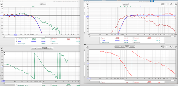
Apologies, but I am still a bit new to this - Let us say one wants to design a crossover response with properties that include the natural roll-off of a driver in the enclosure (two way system)
We can use REW EQ to fit the unfiltered driver response to a target HP or LP filter (say 4th order LR) i.e. determine the filter cut-off frequency, Q, and filter order to have the combination of filter response and driver response match the desired LR4 frequency response.
But what about phase - it would be good to have the target phase response in the lower EQ window also.
 
Arguably redundant, since the system should be minimum phase or very close to it through that region.
 
But one cannot be sure of minimum phase behaviour of a speaker working at its limit, and I do not know by heart what the phase curve of all the various filter types look like. Moreover there will always be small variation between the result and the model frequency response, and although these differences appear small in magnitude, the corresponding phase error can be quite large. Currently I use two computers simultaneously running REW, one for the HP and one for the LP, to visually match the resulting phase curves, and without comparing the resulting phase to the model phase, I am still unsure if the result is proper LR4 or whatever the objective is. In addition to the target phase curve, it would be handy to be able to display the phase curve from another model in the same window. Or even be able to run two EQ windows independently, while displaying the results in a common window.
 
I mention the minimum phase nature of the response since the phase is inextricably linked to the magnitude, so to change one you must change the other (assuming you are not applying all-pass filters). I haven't encountered anyone compromising the magnitude response of a crossover to alter its phase response, but there is much in the world I haven't encountered. Target responses rarely include phase, most are magnitude only, so I'm dubious of the benefit of trying to provide a phase target.
 
This illustrates the challenge - for example attempting to phase match two 48db/oct LR responses crossing at 900hz. There is a decent match to the LR8 frequency response, but the predicted phase is off, theoretically phase should track each other in the crossover region. It is unclear if both or one of them is off. If one could compare predicted phase to target phase or and/or predicted phase of other driver while modelling it would help.
 

Attachments

  • test_LR8.png
    test_LR8.png
    128.7 KB · Views: 48
Difficult to say for sure from those images, but neither phase response looks correct in as much as both look like they may have a component due to time delay, i.e. the t=0 points for the responses are not correct. The group delay plots might show that. Phase is so strongly affected by measurement time delays that it is often difficult to make any meaningful use of it. The Predicted Phase overlay graph lets you more easily compare phase plots, provided the measurements have valid (or at least comparable, sharing a common timing reference) t=0 positions.
 
Your one chart indicates an active XO. If that XO has delay options, i.e., a DSP XO then the phase can be adjusted as needed by adding delay as needed to one of the drivers. If the XO is analog then the adjustment is by either changing the relative driver offset, or adding an all-pass circuit. Either way given REW measurements the REW alignment tool will find the correct adjustment needed for delay or offset. The measurements can or should be in the same mdat file. This post and its thread may be helpful. The requirement requirements for the measurements is also indicated there. I can help out as needed.
 
Indeed it is active crossover, but not DSP. I shall check the thread you refer to, cheers. In my example the timing offsets are removed, but I have found the phase difference is due to a high shelf added in REW EQ as compression driver compensation. This shelf needs both an upper and lower knee (say 2khz,10khz) , but in REW I can only control the upper knee, so the shelf in effect acts as a delay in the crossover region.
 
If you wanted a shelf with a shallower slope the LSQ/HSQ filters allow a lower Q to be used.
 
I tried, but cannot seem to be able to model compression driver (CD) correction in REW. In this case CD correction is by tweaking the HF power amp frequency response, creating something akin to the model showed in the plot.
 

Attachments

  • CD_correction.png
    CD_correction.png
    7.7 KB · Views: 32
Great equivalent, cheers!
 
Back
Top