


-
AUDIO VIDEO PROCESSING, SETUP & ENVIRONMENTOfficial REW (Room EQ Wizard) Support Forum Audiolense User Forum Calibration Equipment Auto-EQ Platforms / Immersive Audio Codecs Video Display Technologies / Calibration AV System Setup and Support Listening Room / Home Theater Build Projects Room Acoustics and Treatments AV Showcase Movies / Music / TV / Streaming
-
AUDIO VIDEO DISCUSSION / EQUIPMENTHome Theater / Audio and Video - Misc Topics Essence For Hi Res Audio AV Equipment Advice and Pricing Awesome Deals and Budget AV Equipment AV Receivers / Processors / Amps UHD / Blu-ray / CD Players / Streaming Devices Two Channel Hi-Fi Equipment DIY Audio Projects Computer Systems - HTPC / Gaming HD and UHD Flat Screen Displays Projectors and Projection Screens AV Accessories Buy - Sell - Trade
Navigation
Install the app
How to install the app on iOS
Follow along with the video below to see how to install our site as a web app on your home screen.
Note: This feature may not be available in some browsers.
More options
You are using an out of date browser. It may not display this or other websites correctly.
You should upgrade or use an alternative browser.
You should upgrade or use an alternative browser.
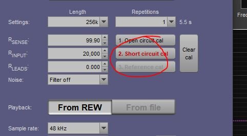
Need Help "Short Circuit Measurement i not Valid"
- Thread starter biogesic
- Start date


John Mulcahy
REW Author
- Joined
- Apr 3, 2017
- Posts
- 8,441
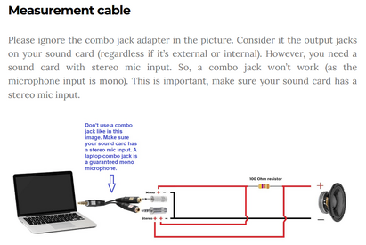
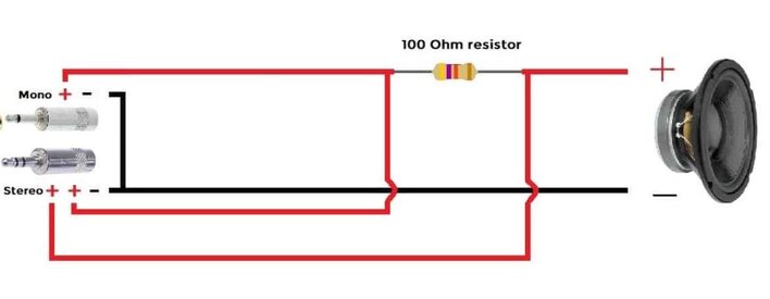
The diagram looks wrong, laptop headset inputs usually have a mono mic input and a stereo headphone output and so are not useable for impedance measurement, which requires a stereo input.
Hi,Hi all, I trying to make the jig for the impedance measurement but Im stuck with calibrating because I always have this error... I dont know what seems to be the problem.. I followed this diagram View attachment 64937View attachment 64938
The diagram posted comes from the "Audio Judgement" website.
You need to read the author's article Measure Thiele Small parameters using free software - Audio Judgement and to watch the "Part 2 : UPDATE video".
It should work.
Attachments
Last edited:
yes Iv seen part 2 but still got the same results. Im using an external soundcardThe diagram looks wrong, laptop headset inputs usually have a mono mic input and a stereo headphone output and so are not useable for impedance measurement, which requires a stereo input.
Last edited:
Thanks, I was following the diagram for the cable and using this external soundcard for the input and output.... also tried this diagram from the site and also gives me the same error....The diagram looks wrong, laptop headset inputs usually have a mono mic input and a stereo headphone output and so are not useable for impedance measurement, which requires a stereo input.
Attachments
Last edited:
Have you confirmed basic loopback measurement is ok from your designated output to separately each designated input ? That should confirm that you have assigned the inputs and outputs in REW 'Preferences' control correctly.
tried swapping loopback but still have the same results and cant go thru number 2 cal.Have you confirmed basic loopback measurement is ok from your designated output to separately each designated input ? That should confirm that you have assigned the inputs and outputs in REW 'Preferences' control correctly.
Attachments
Were you able to do a frequency measurement sweep from the designated output, looped back to the designated input, and see a flat-line amplitude and phase response, and where that frequency response changed levels as the output signal level was varied using soundcard settings? And similar for other input channel, and similar for when the input gain control is varied on the soundcard?
John Mulcahy
REW Author
- Joined
- Apr 3, 2017
- Posts
- 8,441
For the soundcard use line in and headphone out. Both require stereo jack plugs.
I managed to solved the issues and successfully getting it to work for few weeks and yesterday I cleared cal and tried to calibrate again but now I get lots of errors and cant get pass 1st cal and cant get the input levels the same...For the soundcard use line in and headphone out. Both require stereo jack plugs.

Attachments
John Mulcahy
REW Author
- Joined
- Apr 3, 2017
- Posts
- 8,441
If that's the open circuit calibration the level should be almost the same on both inputs, which suggests a wiring problem since the measurement input should be getting the same signal as the reference input, just from after the sense resistor.
you're right, I checked the board of my sound card and found out damaged joints , fixed it and its working now.... thank you...If that's the open circuit calibration the level should be almost the same on both inputs, which suggests a wiring problem since the measurement input should be getting the same signal as the reference input, just from after the sense resistor.

paul_timber
Registered
- Joined
- Apr 24, 2024
- Posts
- 3
Hi everyone,
I have the same problem with the impedance calibration in rew. I´m using an external soundcard (Behringer UCA 202) ,which i slightly modified, the Arta Box and an old Pioneer A-604R. At the moment I´m not using a microphone, but that should not be any problem. The open circuit calibration works great, but if i make a short circuit calibration, I get an error. Has anyone any idea how I could fix this? I really tried everything and I still have no clue why it´s not working.


I have the same problem with the impedance calibration in rew. I´m using an external soundcard (Behringer UCA 202) ,which i slightly modified, the Arta Box and an old Pioneer A-604R. At the moment I´m not using a microphone, but that should not be any problem. The open circuit calibration works great, but if i make a short circuit calibration, I get an error. Has anyone any idea how I could fix this? I really tried everything and I still have no clue why it´s not working.
John Mulcahy
REW Author
- Joined
- Apr 3, 2017
- Posts
- 8,441
Follow the REW instructions for calibration, leave the box in impedance mode and do not change any settings on it.
paul_timber
Registered
- Joined
- Apr 24, 2024
- Posts
- 3
Thank´s for the reply.Follow the REW instructions for calibration, leave the box in impedance mode and do not change any settings on it.
I read the instructions again, followed it step by step, but I get the same error again. :/
I also check if the wiring is correct and i could not find any error.
John Mulcahy
REW Author
- Joined
- Apr 3, 2017
- Posts
- 8,441
Something must be set up wrong. When you do the short circuit measurement the load is shorted, so the measurement input is connected to ground through that short while the ref input gets a direct feed from the output. Since the image you posted shows both inputs have almost exactly the same level the measurement input can't be shorted to ground or the sense resistor isn't in circuit.
paul_timber
Registered
- Joined
- Apr 24, 2024
- Posts
- 3
I just measured with a multimeter if the sense resistor is in the circuit and it is. I also check if the wiring of the arta box is correct and I couldn´t find any mistake.Something must be set up wrong. When you do the short circuit measurement the load is shorted, so the measurement input is connected to ground through that short while the ref input gets a direct feed from the output. Since the image you posted shows both inputs have almost exactly the same level the measurement input can't be shorted to ground or the sense resistor isn't in circuit.
Is there any easy solution without the arta box? If there is one and it would work, i would know, that the problem is the arta box.
Or maybe you have any other idea, why it´s not working?
John Mulcahy
REW Author
- Joined
- Apr 3, 2017
- Posts
- 8,441
The minimum circuit is shown in the help, there is very little to it. For it not to work as you have it set up either the switches are in the wrong position (the box should be in impedance mode and on, NOT in cal/off) or something is wrong in the wiring. It should be pretty straightforward to check that when you short the leads where the thing you plan to measure will be connected that you have a good connection to ground right back to the measurement input.
Hi,
Ive got the same problem with my setup.
My soundcard is the Behringer UCA202 and I use a circuit for impedance measurement only. No switches or frequency response related components to simplify my setup.


I tried to switch around every single hardware input and output as well as probably every "preferences" setting.
Java drivers also didnt help here. I do still guess that it is a software issue?
My circuit is wired correctly, I checked multiple times now. Just a 27.15Ohm Rsense with two voltage dividers before and after the Rsense with diodes for soundcard protection. And a 1k resistor for ground to digital ground decoupling. Thats it.
I would be greatful if anyone could recommend a fix for my issue ;D
Ive got the same problem with my setup.
My soundcard is the Behringer UCA202 and I use a circuit for impedance measurement only. No switches or frequency response related components to simplify my setup.
I tried to switch around every single hardware input and output as well as probably every "preferences" setting.
Java drivers also didnt help here. I do still guess that it is a software issue?
My circuit is wired correctly, I checked multiple times now. Just a 27.15Ohm Rsense with two voltage dividers before and after the Rsense with diodes for soundcard protection. And a 1k resistor for ground to digital ground decoupling. Thats it.
I would be greatful if anyone could recommend a fix for my issue ;D
John Mulcahy
REW Author
- Joined
- Apr 3, 2017
- Posts
- 8,441
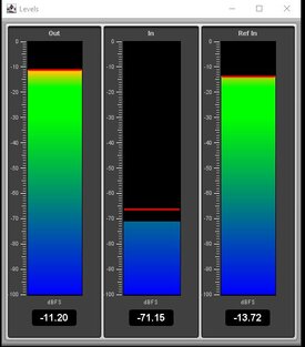
Evidently something is not correct. How could a short-circuited input have an input level of -30 dBFS?My circuit is wired correctly
Thank you for your fast answer.Evidently something is not correct. How could a short-circuited input have an input level of -30 dBFS?
I have not short-circuited the inputs themselves, only the outputs from the load connection.

Short circuit cal:

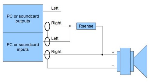
This is my current setup. If I have misunderstood the measurement, a correction would be very helpful or if the circuit does not work like this, that would also be good to know.
John Mulcahy
REW Author
- Joined
- Apr 3, 2017
- Posts
- 8,441
Same question basically, with the load shorted the "Cinch out left" should be connected to ground through the parallel combination of 920R and 1.4k, yet the input is seeing -30 dBFS signal level. Your load ground terminal should be connected to the same ground as the inputs, not passing through the 1k earth bleed.
John Mulcahy
REW Author
- Joined
- Apr 3, 2017
- Posts
- 8,441
You can't make these impedance measurements if your load doesn't share a common ground with the interface, the interface is trying to sense the voltage across the load.
Okay, I have connected both grounds, but the automatic circuit breaker in the amplifier doesn't seem to like that. I get clicking noises every second from the amplifier with simultaneous spikes in the REW input graph. The input resistance on my circuit is 4.5kOhm, i.e. the inputs are not short-circuited. I can't say whether it's due to the Class D amplifier, maybe you need a Class AB or something similar?
What is the minimum circuit for the impedance measurement to work? I will build a new circuit if that is the only way to fix this mess.
What is the minimum circuit for the impedance measurement to work? I will build a new circuit if that is the only way to fix this mess.


Popular tags
20th century fox
4k blu-ray
4k uhd
4k ultrahd
action
adventure
animated
animation
bass
blu-ray
calibration
comedy
comics
denon
dirac
dirac live
disney
dolby atmos
drama
fantasy
hdmi 2.1
home theater
horror
kaleidescape
klipsch
lionsgate
marantz
movies
onkyo
paramount
pioneer
rew
romance
sci-fi
scream factory
shout factory
sony
stormaudio
subwoofer
svs
terror
thriller
uhd
ultrahd
ultrahd 4k
universal
value electronics
warner
warner brothers
well go usa