Help treating my listening room

ddude003

Senior AV Addict
Joined
Aug 13, 2017
Posts
1,640
Location
Somewhere Northeast of Kansas City Missouri
More  
Preamp, Processor or Receiver
PrimaLuna Dialogue Premium TubePre (2 channel+sub)
Main Amp
McIntosh MC152 SS Amp (2 channel)
Additional Amp
Yamaha RX-A850 Pro (the other 5 channels lol)
DAC
Chord Electronics Ltd. Qutest
Computer Audio
MacBook Pro, Custom i7 7700k De-lid 2xAsus1080ti GFX, Audirvana Studio, Hang Loose Convolver, Tone Projects Michelangelo, Pulsar Massive & 8200, LiquidSonics, SoX
Universal / Blu-ray / CD Player
Sony UBP-X700 /M Ultra HD 4K HDR & PS5
Streaming Equipment
Netgear Nighthawk S8000 Streaming Switch, Lumin U1 Mini Streamer Transport
Streaming Subscriptions
QoBuz Studio Premier, Amazon Prime & Netflix
Front Speakers
Martin Logan ElectroMotion ESL
Center Channel Speaker
Martin Logan Motion C2
Surround Speakers
Martin Logan Motion 4
Surround Back Speakers
Martin Logan Motion 4 (yes, another set of these)
Subwoofers
Martin Logan Dynamo 700
Other Speakers
Cifte 12AU7 NOS & Genalex Gold Lion Tubes in Pre
Screen
Elite Screens Aeon CLR3 0.8 Gain 103-inch
Video Display Device
Samsung The Premiere LSP7T UST Laser Projector
Remote Control
PrimaLuna, Lumin iApp, Samsung & Yamaha
Other Equipment
ThrowRug, SaddleBlankets, WideBand & Bass Traps...
Thank you Adhock, suspended panel and limp mass absorbers is another fun area that will drive Horacio crazy... 8^) And the sound flow software looks interesting... Is that 30 day trial full functioning?
 

Matthew J Poes

AV Addict
Joined
Oct 18, 2017
Posts
1,904
Thank you Adhock, suspended panel and limp mass absorbers is another fun area that will drive Horacio crazy... 8^) And the sound flow software looks interesting... Is that 30 day trial full functioning?

Soundflow is the more precise software I have. It’s a silly chunk of change, nothing something worth buying unless you plan on testing panels for detail. I was able to leverage a job to get someone else to essentially cover the cost for me.

I think the trial works but is limited. I forget in what way.
 

ddude003

Senior AV Addict
Joined
Aug 13, 2017
Posts
1,640
Location
Somewhere Northeast of Kansas City Missouri
More  
Preamp, Processor or Receiver
PrimaLuna Dialogue Premium TubePre (2 channel+sub)
Main Amp
McIntosh MC152 SS Amp (2 channel)
Additional Amp
Yamaha RX-A850 Pro (the other 5 channels lol)
DAC
Chord Electronics Ltd. Qutest
Computer Audio
MacBook Pro, Custom i7 7700k De-lid 2xAsus1080ti GFX, Audirvana Studio, Hang Loose Convolver, Tone Projects Michelangelo, Pulsar Massive & 8200, LiquidSonics, SoX
Universal / Blu-ray / CD Player
Sony UBP-X700 /M Ultra HD 4K HDR & PS5
Streaming Equipment
Netgear Nighthawk S8000 Streaming Switch, Lumin U1 Mini Streamer Transport
Streaming Subscriptions
QoBuz Studio Premier, Amazon Prime & Netflix
Front Speakers
Martin Logan ElectroMotion ESL
Center Channel Speaker
Martin Logan Motion C2
Surround Speakers
Martin Logan Motion 4
Surround Back Speakers
Martin Logan Motion 4 (yes, another set of these)
Subwoofers
Martin Logan Dynamo 700
Other Speakers
Cifte 12AU7 NOS & Genalex Gold Lion Tubes in Pre
Screen
Elite Screens Aeon CLR3 0.8 Gain 103-inch
Video Display Device
Samsung The Premiere LSP7T UST Laser Projector
Remote Control
PrimaLuna, Lumin iApp, Samsung & Yamaha
Other Equipment
ThrowRug, SaddleBlankets, WideBand & Bass Traps...
Soundflow is the more precise software I have. It’s a silly chunk of change, nothing something worth buying unless you plan on testing panels for detail. I was able to leverage a job to get someone else to essentially cover the cost for me.

I think the trial works but is limited. I forget in what way.

Seems a bit pricy for DYI use... Reasonable for Pro use...
 

Matthew J Poes

AV Addict
Joined
Oct 18, 2017
Posts
1,904
Seems a bit pricy for DYI use... Reasonable for Pro use...

It’s not for DIY. It wouldn’t be worth it. It’s for production of panels or testing actual room construction.

When designing acoustic spaces it’s rare you would buy panels and install them. You normally designs the acoustics into the room. It’s not feasible to test this ahead of time, so you have to rely on models. That’s why i have it. I can model panels but i use it to model walls.
 

Horacio Lewinski

New Member
Thread Starter
Joined
May 17, 2018
Posts
57
Horacio, Your welcome... Strictly speaking, a classic Helmholtz resonator is air filled... In my view, filling a Helmholtz resonator with other mass would make it a hybrid device as are your perforated panels containing a 2" fiberglass panel... Assuming the panel is similar to Owens Corning 703/705 Fiberglass Acoustical Board and not a hard nonporous fiberglass plate... So, from my point of view, you may as well fill the thing with any additional mass that is appropriate to absorb bass frequencies... More Fiberglass, Mass Loaded Vinyl or even Activated Carbon as I had suggested before...

Wanders off to contemplate the acoustic properties of Cheetos... ;^)

Whoa! Lots of activity. Great! Sorry I haven't responded - been travelling hecticly.

As Matthew mentioned, the fiberglass inside the Helmhotz resonator is to lower the Q. I just copied what Everest Toole shows in his book, and he notes adding (porous) fiberglass inside widens the frequency band where the resonator...resonates :)

The fiberglass panel is kept 4" away from the wall, and right behind the MDF perforated panel. So indeed the panel acts as a velocity absorber, while the "pure" Helmholtz resonator acts as a pressure absorber.
 

ddude003

Senior AV Addict
Joined
Aug 13, 2017
Posts
1,640
Location
Somewhere Northeast of Kansas City Missouri
More  
Preamp, Processor or Receiver
PrimaLuna Dialogue Premium TubePre (2 channel+sub)
Main Amp
McIntosh MC152 SS Amp (2 channel)
Additional Amp
Yamaha RX-A850 Pro (the other 5 channels lol)
DAC
Chord Electronics Ltd. Qutest
Computer Audio
MacBook Pro, Custom i7 7700k De-lid 2xAsus1080ti GFX, Audirvana Studio, Hang Loose Convolver, Tone Projects Michelangelo, Pulsar Massive & 8200, LiquidSonics, SoX
Universal / Blu-ray / CD Player
Sony UBP-X700 /M Ultra HD 4K HDR & PS5
Streaming Equipment
Netgear Nighthawk S8000 Streaming Switch, Lumin U1 Mini Streamer Transport
Streaming Subscriptions
QoBuz Studio Premier, Amazon Prime & Netflix
Front Speakers
Martin Logan ElectroMotion ESL
Center Channel Speaker
Martin Logan Motion C2
Surround Speakers
Martin Logan Motion 4
Surround Back Speakers
Martin Logan Motion 4 (yes, another set of these)
Subwoofers
Martin Logan Dynamo 700
Other Speakers
Cifte 12AU7 NOS & Genalex Gold Lion Tubes in Pre
Screen
Elite Screens Aeon CLR3 0.8 Gain 103-inch
Video Display Device
Samsung The Premiere LSP7T UST Laser Projector
Remote Control
PrimaLuna, Lumin iApp, Samsung & Yamaha
Other Equipment
ThrowRug, SaddleBlankets, WideBand & Bass Traps...
Matt, It looks like there are three pricing levels available... The Basic level is what I said would be for the DIYer... And I had said it is a bit pricey... And the end user is the arbiter of worth... "The Basic version is intended for beginners who want to become familiar with absorption and transmission loss calculations and are interested in modeling simple structures for applications in advanced home theaters and semi-professional studios."

And I have no experience with that company or its products other than reading whats on their website...

It is my opinion that a Cheeto would be a better low frequency velocity absorber than Corn Doodle Packing Peanut... 8^)
 
Last edited:

Horacio Lewinski

New Member
Thread Starter
Joined
May 17, 2018
Posts
57
Ok a few things to discuss here:

Pressure absorbers (Reactive absorbers as you called them) operate best at the pressure maximum of the mode. That means, at the wall typically. As close to the wall as possible. Increasing the airspace lowers the tuning of the device, but simply moving a sealed pressure absorber away from the wall makes it less effective. With the really low modes that these panels are designed to treat, hitting the next pressure maximum would mean like 1/3 into the room or even half way into the room, not exactly convenient.

For velocity absorbers, porous fiberglass panels, these work better at the velocity maximum, which is away from the wall. This is why they work so much more efficiently the farther they are from the wall (thought eventually if the distance from the wall relative to their thickness and flow resistivity becomes great you get comb filtering. These should be spaced away from a wall (and they need to have an open back) but maybe not 1 foot from the wall unless they are built for that.

Adding a membrane of low mass to the front of a velocity absorber only slightly changes their mode of operation. At low frequencies, the added mass causes a greater reactive force against the LF wave than the fiberglass would otherwise have. Think of it as the equivalent of stiffening the spring of a suspension, with the fiberglass managing the damping still. At certain frequencies, the low mass means sound still mostly passes through the membrane and hits the fiberglass being dissipated. At higher frequencies, it reflects. This is still primarily acting like a velocity absorber and they have wide bandwidth.

Place a high mass in front of the fiberglass and suddenly that mass will dominate in the system, making it act better on the high pressure of the wave, rather than the velocity. The fiberglass is still acting as damping and it is still a spring-mass system, but the mass is now that front membrane or panel. The panel is also self-damping, which is why it works with no fiberglass as well.

Keep in mind that a Helmholtz is still a spring-mass system. The air in those holes is the mass. That mass is no different than the placement of a physical mass such as a sheet of plywood on the front.

All of this operates by converting energy from one form to another. From sound vibrations to heat.

Placing a 4" cloth covered panel against a wall isn't that effective at LF's, it just isn't efficient. That is a velocity absorber attempting to convert sound energy to heat energy where the conversion method is least efficient. Think of it as a car, you want to get the best gas mileage and you are cruising along at 55 mph in 3rd gear with the engine turning at 3500 rpms. The efficient zone is 1700rpms, you need to shift to a lower gear to get good gas mileage or slow down. With a velocity absorber, it isn't efficient against the wall, so you need to either move it outward or accept its absorption only at higher frequencies. Increasing flow resistivity increases efficiency for shallow depth panels to a point, but it has its limits.

http://www.acousticmodelling.com/
Playing around with these apps can be helpful to see all of this. I've always loved this site. It has great free tools. It doesn't model multi-layer panels correctly, but everything else is close enough.

Just to be sure: on post #65 I was referring to building a pressure absorber in the corner.

But maybe I'm better off dedicating that corner space to a velocity absorber (4" fiberglass panel about 4" away from wall, floor to ceiling, 70cm width. And make a pressure absorber between the Helmholtz resonator you see in the picture and the air conditioner, about 4 feet tall by 10 feet wide and about 2.5" thick (1/2" MDF panel against 2" fiberglass panel against wall).

The pistonic behavior is a good point, and could be addressed by holding the MDF by a frame that holds it in place rather than screwing or other fixing means along the edges.

BTW, the white panel doors seen on the picture in the first post also act as pressure absorbers, but od course are in the middle of the room.
 

Matthew J Poes

AV Addict
Joined
Oct 18, 2017
Posts
1,904
Just to be sure: on post #65 I was referring to building a pressure absorber in the corner.

But maybe I'm better off dedicating that corner space to a velocity absorber (4" fiberglass panel about 4" away from wall, floor to ceiling, 70cm width. And make a pressure absorber between the Helmholtz resonator you see in the picture and the air conditioner, about 4 feet tall by 10 feet wide and about 2.5" thick (1/2" MDF panel against 2" fiberglass panel against wall).

The pistonic behavior is a good point, and could be addressed by holding the MDF by a frame that holds it in place rather than screwing or other fixing means along the edges.

BTW, the white panel doors seen on the picture in the first post also act as pressure absorbers, but od course are in the middle of the room.

Hi Horacio,

While technically true, I would be careful about treating any object as an acoustic treatment. It is better to look at it as an unknown. Without careful testing it is unclear what it is doing and if that is a good thing. Technically a closet in a room with the door partially open is a Helmholtz absorber, but that doesn't mean it should be treated as an absorber unless its properties are known. For example, my own closet has a Helmholtz resonance of around 80-100hz and operates over a bandwidth of .5 octaves. However, it's estimated absorption coefficient is only like .2 or so. Nothing too useful (nor do I need a 100hz absorber in the corner of my room).

As for placing a velocity absorber in the corner, that is up to you, but it might be better. Velocity absorbers absorb over a very wide bandwidth. Their efficiency related to size isn't great, but in a corner, you can build a giant absorber. That can be good.

The problem with the traps you are trying to use (and why they aren't used as much in home setups or even many commercial setups) is that they are very hard to get right and need to be very large. I know of many field built panel traps that were installed in studios only to have no meaningful impact on the measured performance of the space due to bad design. Many installed by "expert" studio designers who never bothered to do proper testing. I redid a small Chicago studio with after the primary contractor had trouble addressing a mode. He used a Helmholtz resonator that my own in field measurements showed to be extremely peaky (and it's peak missed mode by half an octave). He designed it correctly to a model, but his model was wrong. In my opinion, the studio was built incorrectly and my fixes were very limited. I ultimately used a membrane trap built by a reputable manufacturer so I could be assured of the results. The system I used was modular and I needed 15 of these membrane traps to get the desired effect.

If you do go this route, you may want to consider using an in situ measurement approach to testing the tuning frequency (and even looking to make the trap tunable). One way to change the tuning of a membrane trap is to change its membrane mass. That isn't that hard, adhering washers to its surface would increase its weight (which isn't such a bad idea for testing). You can also use different thicknesses of MLV if using a material like that. 1/8", 1/4", and 1/2" thickness, for example. To test these in room, you can try the standardized approach for in-room absorption measurement. This involves taking a measurement of the surface with and without the treatment at 0-degree angle. You need a source (subwoofer) firing at the surface at a specified distance, say 2 meters. You need the mic between the source and surface. The difference between the two measurements reflects the absorption and should match the absorption curve (and ultimately can be converted to an absorption coefficient). I have a paper on how to do this somewhere. I think that to do this right, you should ideally build a replacement test specimen equal in height to the thickness of the membrane trap, but maybe not, it isn't actually specified, just makes sense to me. You might try covering the panel with plywood temporarily to see as well.

All of this is why I prefer, whenever possible, to build the room as a treatment in the first place. It's amazing how difficult it is to add significant LF absorption after the fact. Much easier to do so in the design.

Here is a little explanation of how my preferred approach has been shown to provide LF damping. If you consider the LF damping provided, and that in rooms like mine, 5 of the 6 barriers in the room is 100% a bass trap, that is a lot of bass damping!
 

Horacio Lewinski

New Member
Thread Starter
Joined
May 17, 2018
Posts
57
http://www.acousticmodelling.com/
Playing around with these apps can be helpful to see all of this. I've always loved this site. It has great free tools. It doesn't model multi-layer panels correctly, but everything else is close enough.

BTW, super helpful tool!!

I revisited the Helmholtz absorber calculations I did per Toole. Turns out the resonant frequency was spot on, but I misplaced the fiberglass panel. I placed it right behind the perforated panel, so air gap 1=0 and air gap 2=95mm, while absorbent thickness is 50mm, yielding a resonant frequency of 38Hz (as expected) and an absorption coefficient of about 0.17-0.18 wide a wide Q. However, if in the same box I place the same absorbent panel against the back wall by having air gap 1=95 and air gap 2=0, the resonant frequency of course stays at 38Hz but the coefficient goes up to 0.9 and narrow Q. So need to tweak my absorbers!!

BTW, do you know what the flow resistivity of fiberglass panel is? I left the default value as it was a constant for my alternatives anyway.

Thank you!!
 

Matthew J Poes

AV Addict
Joined
Oct 18, 2017
Posts
1,904
BTW, super helpful tool!!

I revisited the Helmholtz absorber calculations I did per Toole. Turns out the resonant frequency was spot on, but I misplaced the fiberglass panel. I placed it right behind the perforated panel, so air gap 1=0 and air gap 2=95mm, while absorbent thickness is 50mm, yielding a resonant frequency of 38Hz (as expected) and an absorption coefficient of about 0.17-0.18 wide a wide Q. However, if in the same box I place the same absorbent panel against the back wall by having air gap 1=95 and air gap 2=0, the resonant frequency of course stays at 38Hz but the coefficient goes up to 0.9 and narrow Q. So need to tweak my absorbers!!

BTW, do you know what the flow resistivity of fiberglass panel is? I left the default value as it was a constant for my alternatives anyway.

Thank you!!

Fiberglass panel like OC 703 is going to be between 20,000 and 50,000. 6lb density Fire Safing mineral board (the stuff sometimes available at normal hardware stores) is like 10,000 to 15,000. Normal insulation is more like 5,000. I believe that rigid mineral board in the 8lb density is like 100,000, but I might have that off. There are websites with some of this data floating around, but it isn't all accurate. Also these panels tend to be a little inconsistent. For example, a lot of different numbers exists for the OC703 and OC705, and I've been told they are all correct, it just depended on who measured them and when.

Moving the placement of the fiberglass in the panel does make a difference. It is because it acts on a different part of the spring-mass system. Placed in the back of the absorber, and it damps the chamber itself. Place it near the perforated panel and it damps the port itself (like damping the neck of a classic Helmholtz resonator. There is nothing wrong with damping the throat, but fiberglass is of too high density for this purpose. Try building a multi-layer panel with a lighter density insulation of like 500 or 1000 near the panel (and no air gap) and see what you get.
 

Horacio Lewinski

New Member
Thread Starter
Joined
May 17, 2018
Posts
57
BTW, super helpful tool!!

I revisited the Helmholtz absorber calculations I did per Toole. Turns out the resonant frequency was spot on, but I misplaced the fiberglass panel. I placed it right behind the perforated panel, so air gap 1=0 and air gap 2=95mm, while absorbent thickness is 50mm, yielding a resonant frequency of 38Hz (as expected) and an absorption coefficient of about 0.17-0.18 wide a wide Q. However, if in the same box I place the same absorbent panel against the back wall by having air gap 1=95 and air gap 2=0, the resonant frequency of course stays at 38Hz but the coefficient goes up to 0.9 and narrow Q. So need to tweak my absorbers!!

BTW, do you know what the flow resistivity of fiberglass panel is? I left the default value as it was a constant for my alternatives anyway.

Thank you!!

Sorry I've been MIA. Work load has gone over the top and been travelling a lot.

Somehow, when I wrote the above post I got confused with where I had really placed the fiberglass panel within the Helmholtz perforated panel resonators. I had in fact placed them where they should have been: against the back panel, so against the wall. Hence I'm getting as much absorption as I can from these. Toole's and acousticmodelling.com align.
 

Horacio Lewinski

New Member
Thread Starter
Joined
May 17, 2018
Posts
57
Hi Horacio,

While technically true, I would be careful about treating any object as an acoustic treatment. It is better to look at it as an unknown. Without careful testing it is unclear what it is doing and if that is a good thing.

I completely agree. Hopefully you can yield light on one issue I can't figure out along these lines: My left wall is a floor-to-ceiling, front-to-back wall glass sliding panel doors. Single glass doors. In my mind such thin glass would be basically invisible to low frequencies and the whole wall would be a bass trap as bass would leave the room and don't bounce back. Yet my measurements show very long decay times in the low end...why is this?

Moreover, each glass panel could be thought of as a pressure absorber held in place by the 4 edges, pretty dense panel, further acting to absorb low end. Yet the long decay is there...
 

ddude003

Senior AV Addict
Joined
Aug 13, 2017
Posts
1,640
Location
Somewhere Northeast of Kansas City Missouri
More  
Preamp, Processor or Receiver
PrimaLuna Dialogue Premium TubePre (2 channel+sub)
Main Amp
McIntosh MC152 SS Amp (2 channel)
Additional Amp
Yamaha RX-A850 Pro (the other 5 channels lol)
DAC
Chord Electronics Ltd. Qutest
Computer Audio
MacBook Pro, Custom i7 7700k De-lid 2xAsus1080ti GFX, Audirvana Studio, Hang Loose Convolver, Tone Projects Michelangelo, Pulsar Massive & 8200, LiquidSonics, SoX
Universal / Blu-ray / CD Player
Sony UBP-X700 /M Ultra HD 4K HDR & PS5
Streaming Equipment
Netgear Nighthawk S8000 Streaming Switch, Lumin U1 Mini Streamer Transport
Streaming Subscriptions
QoBuz Studio Premier, Amazon Prime & Netflix
Front Speakers
Martin Logan ElectroMotion ESL
Center Channel Speaker
Martin Logan Motion C2
Surround Speakers
Martin Logan Motion 4
Surround Back Speakers
Martin Logan Motion 4 (yes, another set of these)
Subwoofers
Martin Logan Dynamo 700
Other Speakers
Cifte 12AU7 NOS & Genalex Gold Lion Tubes in Pre
Screen
Elite Screens Aeon CLR3 0.8 Gain 103-inch
Video Display Device
Samsung The Premiere LSP7T UST Laser Projector
Remote Control
PrimaLuna, Lumin iApp, Samsung & Yamaha
Other Equipment
ThrowRug, SaddleBlankets, WideBand & Bass Traps...
Last edited:

Horacio Lewinski

New Member
Thread Starter
Joined
May 17, 2018
Posts
57
Glass reflects more or less the same as any other nonporous, rigid, smooth surface material...

My point is glass, as any other thin material, should be basically "transparent" to long wavelength frequencies. Of course a dense (such as glass) material will be less transparent than a lighter one, but still at 40Hz the wavelength is so large compared to the thickness of glass that they should go right through.

What you describe, including first reflection points is true and applicable much higher in frequencies, at least above 300Hz.

I would expect the low frequencies to just leave through the window, so to speak, decreasing decay time. But it doesn't happen that way and can't figure out why.
 

ddude003

Senior AV Addict
Joined
Aug 13, 2017
Posts
1,640
Location
Somewhere Northeast of Kansas City Missouri
More  
Preamp, Processor or Receiver
PrimaLuna Dialogue Premium TubePre (2 channel+sub)
Main Amp
McIntosh MC152 SS Amp (2 channel)
Additional Amp
Yamaha RX-A850 Pro (the other 5 channels lol)
DAC
Chord Electronics Ltd. Qutest
Computer Audio
MacBook Pro, Custom i7 7700k De-lid 2xAsus1080ti GFX, Audirvana Studio, Hang Loose Convolver, Tone Projects Michelangelo, Pulsar Massive & 8200, LiquidSonics, SoX
Universal / Blu-ray / CD Player
Sony UBP-X700 /M Ultra HD 4K HDR & PS5
Streaming Equipment
Netgear Nighthawk S8000 Streaming Switch, Lumin U1 Mini Streamer Transport
Streaming Subscriptions
QoBuz Studio Premier, Amazon Prime & Netflix
Front Speakers
Martin Logan ElectroMotion ESL
Center Channel Speaker
Martin Logan Motion C2
Surround Speakers
Martin Logan Motion 4
Surround Back Speakers
Martin Logan Motion 4 (yes, another set of these)
Subwoofers
Martin Logan Dynamo 700
Other Speakers
Cifte 12AU7 NOS & Genalex Gold Lion Tubes in Pre
Screen
Elite Screens Aeon CLR3 0.8 Gain 103-inch
Video Display Device
Samsung The Premiere LSP7T UST Laser Projector
Remote Control
PrimaLuna, Lumin iApp, Samsung & Yamaha
Other Equipment
ThrowRug, SaddleBlankets, WideBand & Bass Traps...
Is anything stopping you from measuring the other side of the window??? I am sure there is some energy loss thru the window... However, the room and your stereo is a system...
 

Matthew J Poes

AV Addict
Joined
Oct 18, 2017
Posts
1,904
My point is glass, as any other thin material, should be basically "transparent" to long wavelength frequencies. Of course a dense (such as glass) material will be less transparent than a lighter one, but still at 40Hz the wavelength is so large compared to the thickness of glass that they should go right through.

What you describe, including first reflection points is true and applicable much higher in frequencies, at least above 300Hz.

I would expect the low frequencies to just leave through the window, so to speak, decreasing decay time. But it doesn't happen that way and can't figure out why.

At low frequencies it is the rigidity of the wall that stops the transmission of bass, it’s density is completely irrelevant. The crossover frequency from mass to stiffness is the wall resonant frequency. That means low mass walls are dominated by stiffness to higher frequencies.

Glass is stiffer than drywall, but poorly damped. What that should mean is that it would actually contain the Lf’s Better than drywall but will have a sharp resonant frequency that will pass sound readily. I can probably model this and see what I get. You could also measure this, though I’ve learned that measuring TL isn’t as simple as it seems. A simple measurement on each side isn’t totally accurate. I have some special software that lets you scan the wall. It seems to work better. I can’t figure out how it works so I have no idea how to recreate their calculations.

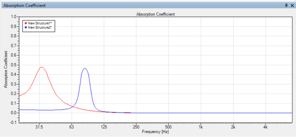
All walls work as bass absorbers. Normal rigid drywall and stud walls have a high q resonance at around 65hz or so (4” depth and no insulation). A damped wall has a lower Q resonance down lower and a shelf where absorption increases. Here’s an example:
F7BCE3A3-AEE4-428C-8D84-98B3C73BB0E7.png

I didn’t create this model for my point here so the lower resonance is also due to a deeper wall structure. I was comparing a normal wall to a proposed rear wall with a 10” gap. The only real difference is that the resonance frequency would move back closer to 60hz but the shelf below the resonance would be less.

This is why I like compound walls so much. You can’t equal that much absorption at such a low frequency with add-on treatments without taking up a ton of space.
 

Horacio Lewinski

New Member
Thread Starter
Joined
May 17, 2018
Posts
57
At low frequencies it is the rigidity of the wall that stops the transmission of bass, it’s density is completely irrelevant. The crossover frequency from mass to stiffness is the wall resonant frequency. That means low mass walls are dominated by stiffness to higher frequencies.

Glass is stiffer than drywall, but poorly damped. What that should mean is that it would actually contain the Lf’s Better than drywall but will have a sharp resonant frequency that will pass sound readily. I can probably model this and see what I get. You could also measure this, though I’ve learned that measuring TL isn’t as simple as it seems. A simple measurement on each side isn’t totally accurate. I have some special software that lets you scan the wall. It seems to work better. I can’t figure out how it works so I have no idea how to recreate their calculations.

All walls work as bass absorbers. Normal rigid drywall and stud walls have a high q resonance at around 65hz or so (4” depth and no insulation). A damped wall has a lower Q resonance down lower and a shelf where absorption increases. Here’s an example:
View attachment 9299

I didn’t create this model for my point here so the lower resonance is also due to a deeper wall structure. I was comparing a normal wall to a proposed rear wall with a 10” gap. The only real difference is that the resonance frequency would move back closer to 60hz but the shelf below the resonance would be less.

This is why I like compound walls so much. You can’t equal that much absorption at such a low frequency with add-on treatments without taking up a ton of space.


Thank you Matthew.

What would be a compound wall?

In my room the front and back walls are brick, left is glass, right is acoustic barrier heavy door (1/4" mdf, 5mm "rubber" acoustic barrier, 2" fiberglass panel, 1/4" mdf). Maybe I want to go to a compound wall built agains the brick wall?
 

Matthew J Poes

AV Addict
Joined
Oct 18, 2017
Posts
1,904
Thank you Matthew.

What would be a compound wall?

In my room the front and back walls are brick, left is glass, right is acoustic barrier heavy door (1/4" mdf, 5mm "rubber" acoustic barrier, 2" fiberglass panel, 1/4" mdf). Maybe I want to go to a compound wall built agains the brick wall?

A compound wall just means one that you build up to serve a certain acoustic purpose. When you build a room from scratch you can come up with a room ratio that is ideal for well spread modes. Then you can look at the dominants modes in such a room and identify the tuning frequency of the modes for each wall. For example, the back wall of a room should ideally be tuned to the lowest longitudinal mode. 22hz in my case. The front wall should be tuned low as well but then you want it to be able to address SBIR and Hf reflections. You add layers to the wall in the form of Velocity absorbers. Since you want the absorption to still favor LF’s, I suggest alternating layers of fiberglass and a membrane. The surface can be exposed fiberglass, a solid membrane, or a micro-perf membrane. This would just depend on what you are doing. Your initial acoustic measurements would dictate exactly which materials are used in which way.

So a compound wall is just a wall built up in layers such that it’s entirety acts as a treatment. Technically a normal drywall structure with a 4” fiberglass panel is a compound wall but it wouldn’t be a very good one.
 

Horacio Lewinski

New Member
Thread Starter
Joined
May 17, 2018
Posts
57
A compound wall just means one that you build up to serve a certain acoustic purpose. When you build a room from scratch you can come up with a room ratio that is ideal for well spread modes. Then you can look at the dominants modes in such a room and identify the tuning frequency of the modes for each wall. For example, the back wall of a room should ideally be tuned to the lowest longitudinal mode. 22hz in my case. The front wall should be tuned low as well but then you want it to be able to address SBIR and Hf reflections. You add layers to the wall in the form of Velocity absorbers. Since you want the absorption to still favor LF’s, I suggest alternating layers of fiberglass and a membrane. The surface can be exposed fiberglass, a solid membrane, or a micro-perf membrane. This would just depend on what you are doing. Your initial acoustic measurements would dictate exactly which materials are used in which way.

So a compound wall is just a wall built up in layers such that it’s entirety acts as a treatment. Technically a normal drywall structure with a 4” fiberglass panel is a compound wall but it wouldn’t be a very good one.

Thank you Matthew.

Those guidelines were super helpful. If I look at the first length fundamental it's 36Hz, and looking at the wavelet I posted on post #46 we can see around 36Hz I have the highest decay time. Great! So now I know what I should design for and why that's the problem frequency!

In fact the perforated panel absorbers I built were designed for 38Hz, so the design frequency is good, but probably the panels are not large enough to make enough of an impact. I could cover the whole wall with them. They are 12mm thick (the perforated panel), 0.13% perforated area. Sounds a lot simpler than the compound wall you described so likely has shortcomings.
 

Matthew J Poes

AV Addict
Joined
Oct 18, 2017
Posts
1,904
Thank you Matthew.

Those guidelines were super helpful. If I look at the first length fundamental it's 36Hz, and looking at the wavelet I posted on post #46 we can see around 36Hz I have the highest decay time. Great! So now I know what I should design for and why that's the problem frequency!

In fact the perforated panel absorbers I built were designed for 38Hz, so the design frequency is good, but probably the panels are not large enough to make enough of an impact. I could cover the whole wall with them. They are 12mm thick (the perforated panel), 0.13% perforated area. Sounds a lot simpler than the compound wall you described so likely has shortcomings.

No real shortcomings. It’s possible that placing a tuned trap onto an existing wall could have undesirable traits and it takes up a bit more space. Otherwise no problems. The only reason to do it my way is that if you are building a room from scratch, why not. Studios are built from scratch as are custom theaters. Often that lets us dictate the wall placement and construction type. Where possible I always prefer this, but it’s rare. While I’m doing one with a client for a 2-channel room, I’d be surprised if I get any more jobs like this for a while.

If I could only convince people to spend money on custom rooms instead of cable elevators. Much bigger bang for the buck tweak.
 

Horacio Lewinski

New Member
Thread Starter
Joined
May 17, 2018
Posts
57
No real shortcomings. It’s possible that placing a tuned trap onto an existing wall could have undesirable traits and it takes up a bit more space. Otherwise no problems. The only reason to do it my way is that if you are building a room from scratch, why not. Studios are built from scratch as are custom theaters. Often that lets us dictate the wall placement and construction type. Where possible I always prefer this, but it’s rare. While I’m doing one with a client for a 2-channel room, I’d be surprised if I get any more jobs like this for a while.

If I could only convince people to spend money on custom rooms instead of cable elevators. Much bigger bang for the buck tweak.

Been playing around with http://www.acousticmodelling.com/
My idea is to completely cover the front wall with an absorber. Below I played around with limp membrane, but mostly with perforated panel absorbers. Considering the wavelet from post #46 and considering the simulations, which one do you think looks best for my case?
Jul 13 2018 wavelet.jpg
Slide1.JPG
Slide2.JPG
Slide3.JPG
Slide4.JPG
Slide5.JPG
Slide6.JPG
 
Last edited:

Matthew J Poes

AV Addict
Joined
Oct 18, 2017
Posts
1,904
If you were my client and I was making recommendations I would actually not make a recommendation based on the currently available information. I still don’t know what is causing your peaks.

You can’t treat tunes traps like PEQ filters. Unlike eq filters which precondition the signal and this ensure that whatever you measured will be adjusted accordingly, absorbers work on he specific cause of the peak or dip in the first place. That means you have to identify what the cause is.

If you made a trap tunes to roughly 65hz on the front wall it might fix things. The presumption then is that it’s either a length mode or SBIR effect off the front wall. If that isn’t true the panel will end up doing more harm than good.

If you really want to go down the road of a giant wall of tuned traps I would first confirm that wall is the cause. I would model the room and see what aligns best with the peaks. See if you can make REW’s room modeler match and then play around with absorption and speaker placement to make it go away. If adding absorption to the front wall makes it go away then you are on the right track. If not, this might not be the right solution.

The other option is to build a different kind of trap. You might consider one that tunes it’s self to the room. These are more like what GIK make and rely on the tympanic resonances of a membrane to improve LF absorption without relying on a tuned resonance. In other words, build a 4”-6” thick velocity absorber using a good higher density insulation. Apply a membrane over the front that is more like the thickness of pvc or vinyl acetate sheeting. I have used carpet protection film for this. Cover and fabric and mount in your wall.
 

Horacio Lewinski

New Member
Thread Starter
Joined
May 17, 2018
Posts
57
If you were my client and I was making recommendations I would actually not make a recommendation based on the currently available information. I still don’t know what is causing your peaks.

You can’t treat tunes traps like PEQ filters. Unlike eq filters which precondition the signal and this ensure that whatever you measured will be adjusted accordingly, absorbers work on he specific cause of the peak or dip in the first place. That means you have to identify what the cause is.

If you made a trap tunes to roughly 65hz on the front wall it might fix things. The presumption then is that it’s either a length mode or SBIR effect off the front wall. If that isn’t true the panel will end up doing more harm than good.

If you really want to go down the road of a giant wall of tuned traps I would first confirm that wall is the cause. I would model the room and see what aligns best with the peaks. See if you can make REW’s room modeler match and then play around with absorption and speaker placement to make it go away. If adding absorption to the front wall makes it go away then you are on the right track. If not, this might not be the right solution.

Now I'm confused.
My length first mode is 34.5 Hz. The first width mode is 36Hz, although the glass wall and the panel wall might make things funny around this one. But it seems logical to conclude the high decay time in the wavelet at about 35Hz is caused by room modes. Right? I was following this reasoning you lead me through in prior posts, and concluded I should design an absorber with a target frequency of 35Hz. And played with the modelling tool to come up with different flavors of such an absorber (higher peak absorption vs wider coverage).

What am I missing?
 

Matthew J Poes

AV Addict
Joined
Oct 18, 2017
Posts
1,904
Now I'm confused.
My length first mode is 34.5 Hz. The first width mode is 36Hz, although the glass wall and the panel wall might make things funny around this one. But it seems logical to conclude the high decay time in the wavelet at about 35Hz is caused by room modes. Right? I was following this reasoning you lead me through in prior posts, and concluded I should design an absorber with a target frequency of 35Hz. And played with the modelling tool to come up with different flavors of such an absorber (higher peak absorption vs wider coverage).

What am I missing?

Sorry about that Horacio. We were looking at different issues. Yes I think you are right. At those low frequencies this panel approach should work well on those lowest modes.

I was speaking to the peaks in the response at 65hz or so. I think those might be SBIR effects but could also be some kind of modal effect. I was actually measuring a room yesterday that had a similar effect but only to the left or right of the medial positions. All medial positions were nearly flat, but even 12” to either side would lead to a big 6dB boost.

As for which design, i suspect they all will work well. The Helmholtz designs with perforated fronts will actually absorb more mid frequencies that might be a good thing. I might go that route.
 

Horacio Lewinski

New Member
Thread Starter
Joined
May 17, 2018
Posts
57
Sorry about that Horacio. We were looking at different issues. Yes I think you are right. At those low frequencies this panel approach should work well on those lowest modes.

I was speaking to the peaks in the response at 65hz or so. I think those might be SBIR effects but could also be some kind of modal effect. I was actually measuring a room yesterday that had a similar effect but only to the left or right of the medial positions. All medial positions were nearly flat, but even 12” to either side would lead to a big 6dB boost.

As for which design, i suspect they all will work well. The Helmholtz designs with perforated fronts will actually absorb more mid frequencies that might be a good thing. I might go that route.

That's good news! Otherwise it meant I wasn't understanding :)

So, towards the 35Hz peak and long decay time: any of the above models strikes you as clearly better?

Regarding the other peak, around 55-65Hz:
- 2nd length mode is at 70Hz
- 2nd width mode (panel door to window) is at 68Hz
- if we assume the panel door does very little, the extension of the room is the same width, so 68Hz would be f3 from brick to glass width.
- SBIR: I'm looking at the subwoofers given their xo at 80Hz. Both subwoofers cones are 68cm from the front wall so not aligning well with this peak as far as I can see. But their cones are 12" and centers are 23cm from the floor, so could be 5/4 of the wavelengths within 60 to 70Hz.
Seems 3 factors are piling up here: 1) f1 length axis, 2) f1 width axis, 3) 5/4 WL from SWs center to floor. Addressing this looks like my next target :)
 
Top Bottom